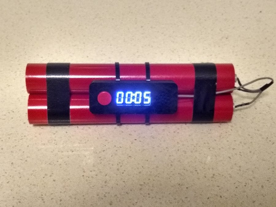
A few weeks ago, I picked up some 20mm PVC pipe that someone had put out for council pickup. On the journey back home, I wondered what I could make with it. This build is what I came up with.
Design (Dynamite)I cut the 20mm PVC pipe into three lengths of 180mm. They were then sprayed with gloss red paint. I designed the end caps and 3D printed them (STL files attached).
The inside of the end caps are painted black and the "fuse" part was painted with silver paint. One of the pipes contains the battery pack. I used one out of a cheap torch that I purchased on eBay.
The wire that I used was from a old VCR that I dismantled. You can also use normal hookup wire. Only one "dynamite stick" contains the battery, the other two are fake and are held onto the "real" wire with a piece of heat-shrink.
The diameter of the "dynamite" determined the overall size of the control unit. I used a 0.36in 4-Digit 7-Segment clock display. There was only enough room to put a button on one side of the display and the buzzer on the other size of the display.
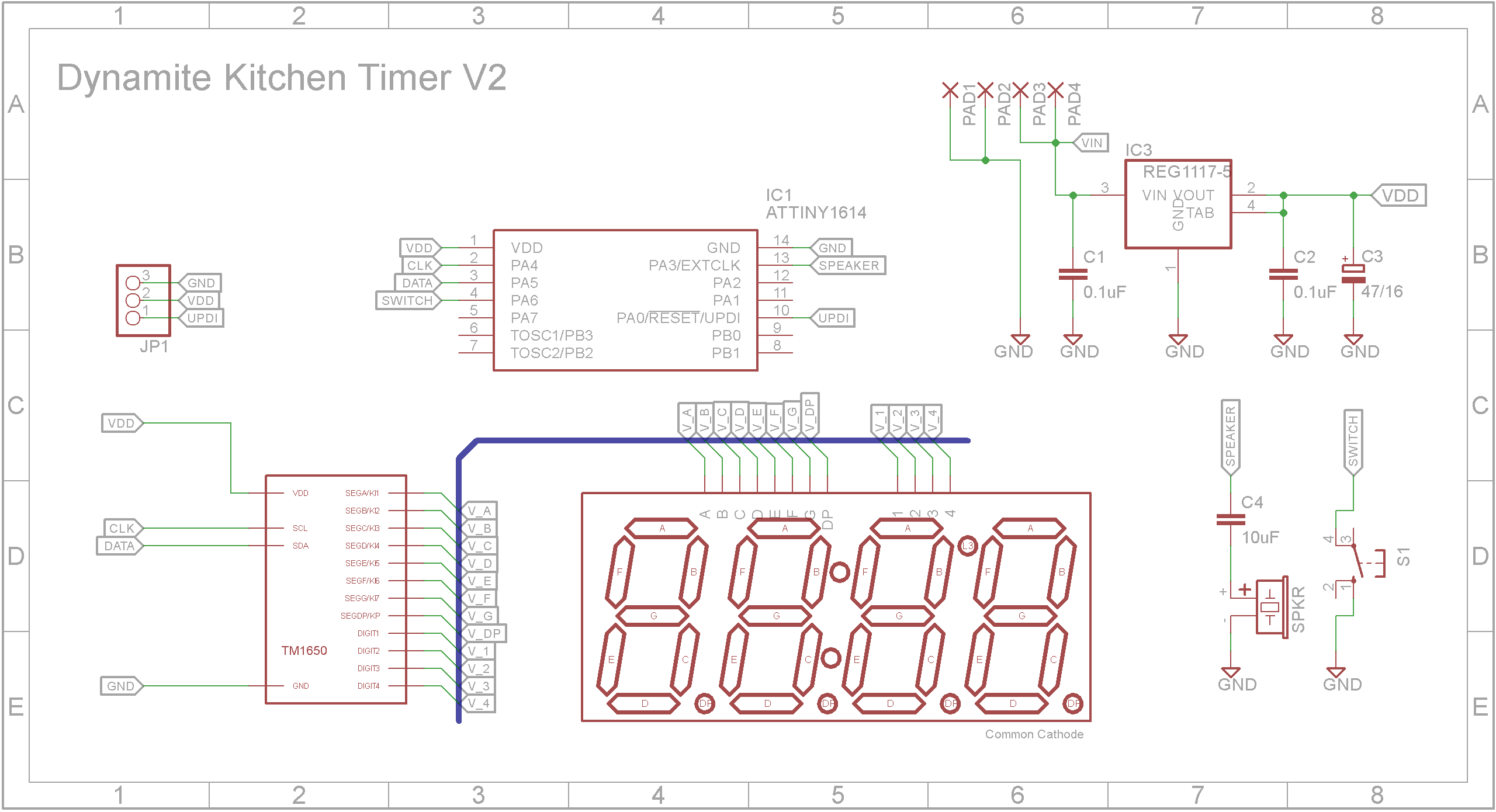
The electronics is built around a ATtiny1614 microprocessor and a TM1650 4-Digit 7-Segment LED driver IC.
With the exception of the switch, display and buzzer, SMD components were used exclusively. The Eagle files have been included should you wish to have the board commercially made or you can do as I did and make it yourself. I used the Toner method.
Start by adding the SMD components. I find it easier to use solder paste rather than use solder from a reel when soldering SMD components.
Add the links if you are using a single sided board.
Add the switch, display and buzzer to the top side of the board. Make sure you put the display in the correct way round. Same goes with the buzzer.
Optionally add a 3-pin right angle header so that you can plug in the UPDI programmer. If you choose to leave it off, you can just tack on some wires until the ATtiny1614 microprocessor is programmed using a UPDI programmer.
You should now program the microprocessor. See the Programming the ATtiny1614 section further on.
3D print the front panel and screw the PCB to it using four 6mm M2 screws.
3D print the bottom of the case and slide two cable ties through the holes provided. Add the top of the case to its bottom.
Insert the end plugs that don't have fuse part into each "dynamite stick".
Tape together the three "dynamite sticks" using black electrical tape. The tape I used started 16mm from each end and was 10mm wide.
Center the unit on the sticks and tighten the cable ties. Cut off any extra cable tie.
Finally insert the battery and insert the end plugs that have the fuse part.
The ATtiny1614 is part of the new breed of ATtiny microprocessors. Unlike the earlier series such as the ATtiny85, the new breed use the RESET pin to program the CPU. To program it you need a UPDI programmer. I made one using a Arduino Nano. You can find complete build instructions at Create Your Own UPDI Programmer. It also contains the instructions for adding the megaTinyCore boards to your IDE.
Connect UPDI programmer and upload sketch
Connect the UPDI programmer
Once the board has been installed in the IDE, select it from the Tools menu.
Select board, chip (ATtiny1614), clock speed (20MHz) and the COM port that the Arduino Nano is connected to.
The Programmer needs to be set to jtag2updi (megaTinyCore).
Open the sketch and upload it to the ATtiny1614.
ConclusionThere is an old saying that one mans rubbish is another mans treasure. A lot of my builds originate from stuff I find on council pick-up day. 😁


_3u05Tpwasz.png?auto=compress%2Cformat&w=40&h=40&fit=fillmax&bg=fff&dpr=2)
Comments
Please log in or sign up to comment.