


Hardware components | ||||||
| × | 1 | ||||
| × | 1 | ||||
 |
| × | 1 | |||
| × | 1 | ||||
 |
| × | 1 | |||
 |
| × | 1 | |||
 |
| × | 1 | |||
 |
| × | 1 | |||
| × | 1 | ||||
| × | 1 | ||||
Software apps and online services | ||||||
 |
| |||||
Hand tools and fabrication machines | ||||||
 |
| |||||
 |
| |||||
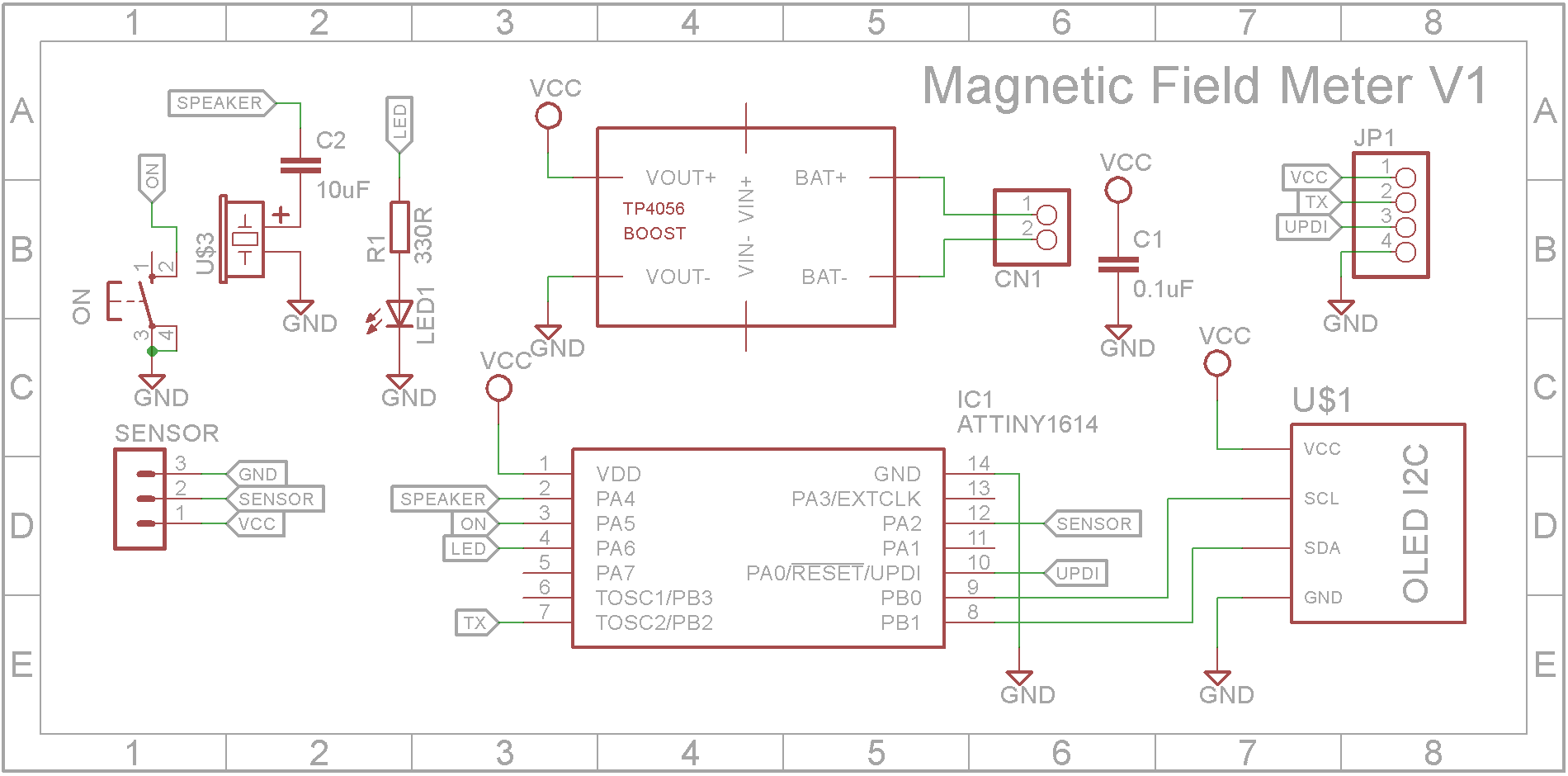
This portable Electromagnetic Field Meter (EMF meter) is a rebuild of Marco Zonca's Magnetic Field Meter range +- 200mT (milliTesla). The hardware has been redesigned to run from a 3.7V Li-ion battery and the software has been updated for the new hardware.
Hardware designThe original version by Marco Zonca used a Arduino Nano. I decided to replace it with a ATtiny1614 microprocessor. This processor has a very low power consumption in sleep mode. The redesign is powered by a 3.7V Li-on battery and includes a J5019 Lithium Battery Boost and Charging module to charge the battery and to provide 5V for the AH3503 Ratiometric Linear Hall Effect Sensor.
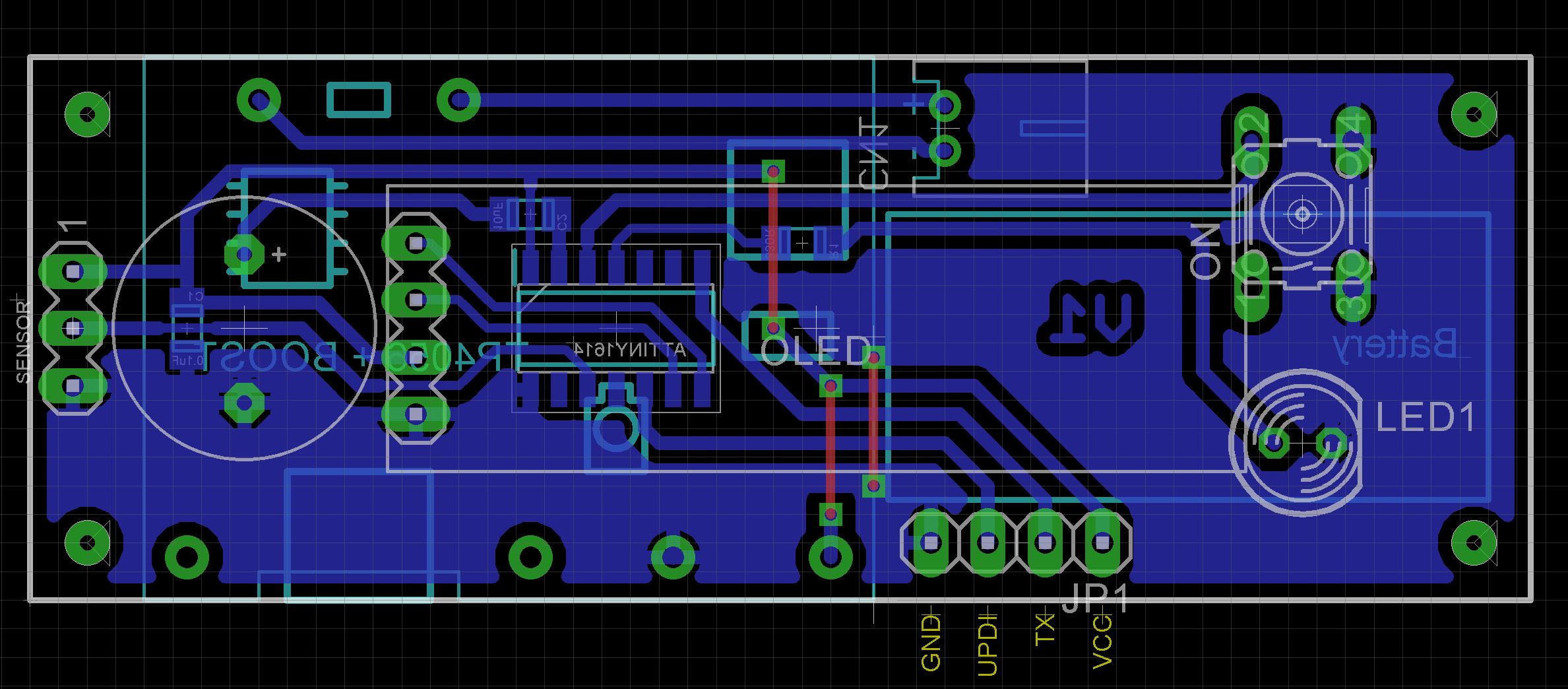
I made a custom PCB to hold the microprocessor and associated connections.
The case is 3D printed using a 0.2mm layer height. Open the STL files in your slicer software or if you don't have a 3D printer, provide them to your local print shop. Supports are not necessary.
The Eagle files are included in case you want to get the board commercially made or you can make it yourself. I used the Toner method to make mine.
Start by adding the SMD components to the board. I find it easier to use solder paste rather than use solder from a reel when soldering SMD components.
Add the links if your board is single-sided.
Add the 4 pin header for the programmer and 6 individual pin headers that the J5019 boost and charger module will be soldered on to. Also add the JST battery socket.
Using Super Glue, glue the button top onto the button. Do not let the glue run down the shaft and into the switch. Solder the button onto the PCB.
Add the active buzzer.
Using Super Glue, glue the two 3D printed spacers to the board and add the 128x32 OLED screen.
Do not add the LED yet.
Solder on the J5019 boost and charger module to the pins you added earlier. Trim off any excess pins.
Place the LED in its holes but don't solder it yet. Make sure it is orientated correctly.
Screw the board into the case using four 6mm M3 screws.
Push the LED to sit on the case. The hole is countersunk so it should seat in the correct location. Solder the LED and cut off any excess leads.
Now will be a good time to program the ATtiny1614 microprocessor. See the next section for more details.
Remove the board from case.
Solder 3 wires to the AH3503 Ratiometric Linear Hall Effect Sensor. Use some heat shrink to ensure the solder joints don't touch when inserting the sensor into the probe end.
Run the wires down the probe shaft and insert the hall effect sensor into the end.
Glue the probe to the case.
Cut and solder the wires to the PCB
Screw the board back into the case.
Unlike the earlier ATtiny series such as the ATtiny85, the ATtiny1614 uses the RESET pin to program the CPU. To program it you need a UPDI programmer. I made one using a Arduino Nano. You can find complete build instructions at Create Your Own UPDI Programmer. It also contains the instructions for adding the megaTinyCore boards to your IDE.
All the components are 5V tolerant so provided the battery is not present, you can power it from the UPDI programmer. If the battery is installed, just connect the GND and UPDI wires and leave off the VCC wire.
Once the board has been installed in the IDE, select it from the Tools menu.
Select the ATtiny1614 board in your IDE
Select Board, Chip, Clock speed, and the COM port that the Arduino Nano is connected to.
The Programmer needs to be set to jtag2updi (megaTinyCore).
Open the sketch and upload it to the ATtiny1614.
Using the EMF meterPressing the button when the unit is off will switch it on.
After the splash screen is displayed, the screen will show the current magnetic field strength in milliteslas.
Bringing the probe near a magnetic field will generate a sound whose volume is based on the signal strength.
The unit will switch off when the probe is not near a magnetic field greater than 5 mT for more than 20 seconds.
The button will zero (or near zero) the instrument. Make sure you are not near a magnetic field when you do this or when you switch the unit on.
Thanks Marco for a delightful project. I'm not sure that I actually have a use for it but it was a fun build in any event. 👍👍👍


Comments