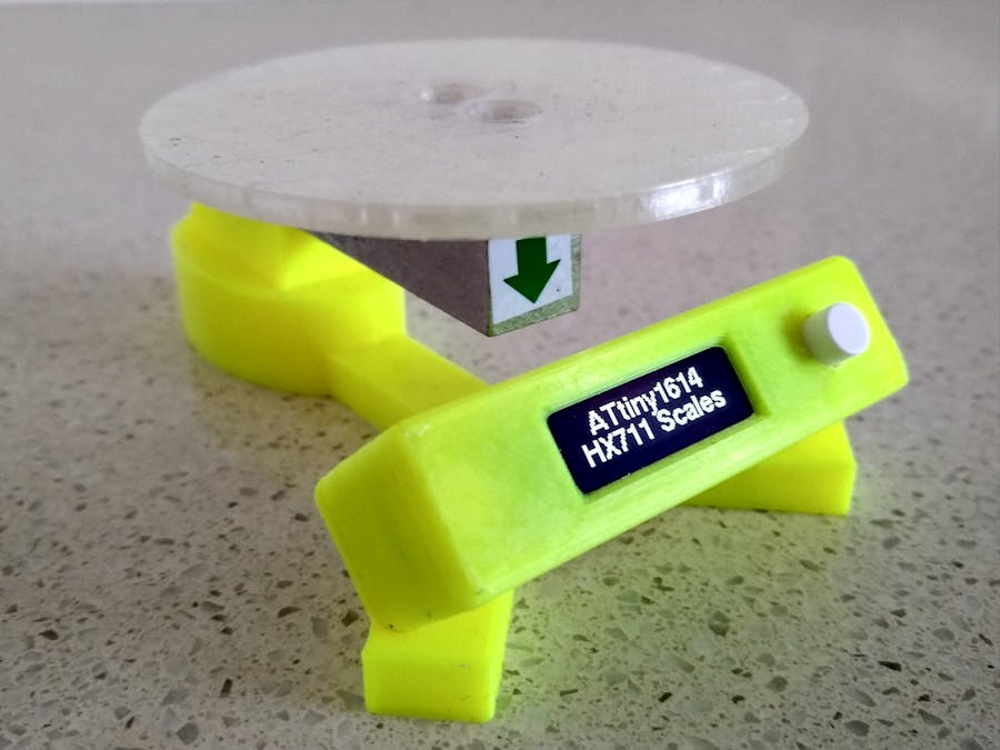
This project came about after reading an article on Load Cells on the Circuit Journal site by Indrek Luuk. A load cell is designed to measure the weight of an object. It is basically an aluminum bar containing 4 resistive strain gauges.
The 4 resistive strain sensors are connected together in a Wheatstone bridge configuration. At rest, the sensors have the same resistance (around 1000 ohms). By placing a 5 volts across the Red/Black wires, the voltage at the Green terminal is 2.5V and the voltage at the White terminal is also 2.5V. The difference in voltage measured by volt meter V is 0V.
As weight is applied to the load cell, the two opposite sensors will change their resistance equally. In the diagram, the red sensors reduce in resistance (less strain applied to them) while the blue sensors increase in resistance (more strain is applied to them). The volt meter measures the difference in voltage across the Green/White nodes. The voltage varies in proportion to the load being applied.
The change in voltage is small so it needs to be amplified and converted to a digital signal so that the microprocessor can read it. This is done via the HX711 module which contains an amplifier and 24 bit analog-to-digital convertor.
Load cells come in different sizes depending on the maximum weight they are designed to measure. Typical sizes are 1/5/10/20/200kg. The number of screw holes, their centers and thread sizes vary depending on the size of the Load Cell.
The 5kg Load Cell and HX711 module costs around AU $5 from Ali-Express.
Demonstration3D printingPrinting is straight forward. Use the following settings in your slicer.
"LoadCellBase V2.stl" - 0.2mm layer height, full supports
"TopPlate V2.stl" - 0.2mm layer height, no supports
"CaseFront.stl" - 0.15mm layer height, no supports
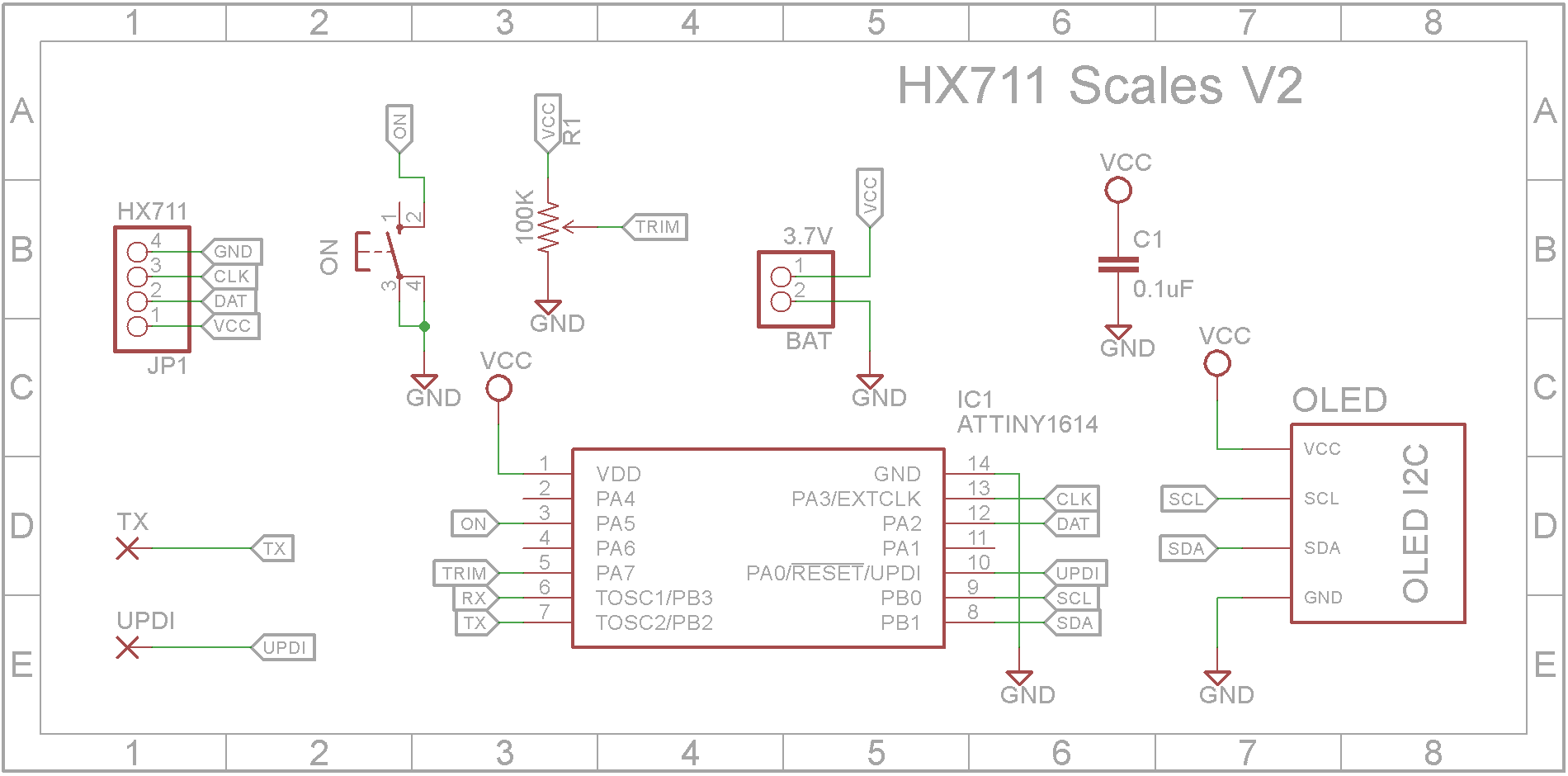
SchematicMost of the hard work is done by the HX711 module. I chose the ATtiny1614 microprocessor due to its low power consumption in sleep mode. The weight is displayed on a 128x32 I2C 0.91in OLED display.
Although this build includes a trim-pot, it ended up being redundant so you can leave it off the board. The idea was to adjust for any variance in the weight displayed should that be necessary.
The PCBTo minimize the space required, the board has been designed to use Surface Mount Devices (SMD) where possible.
The Eagle files have been included should you wish to have the board commercially made or you can do as I did and make it yourself. I used the Toner method.
Assembly - Step 1Start by adding the SMD components. I find it easier to use solder paste rather than use solder from a reel when soldering SMD components. I also used my SMD reflow hot plate that I built a few months back to reflow the solder paste.
Add the links if your board is single-sided.
Add the 4 pin right angle male header for the leads that come in from the HX711 module onto the copper side of the board.
Add the JST battery connector to the copper side of the board.
Glue a spacer to the board to support the OLED display. I used an old pin header with the pins removed as it is the same height as the pin header on the OLED display.
Add the 0.91 in 128x32 OLED display.
Add the 6x6mm tactile switch. It has a 6mm shaft and also add its button cap.
Before adding the PCB to the case, it is easier to program the ATtiny1614 first.
The ATtiny1614 is part of the new breed of ATtiny microprocessors. Unlike the earlier series such as the ATtiny85, the new breed use the RESET pin to program the CPU. To program it you need a UPDI programmer. I made one using a Arduino Nano. You can find complete build instructions at Create Your Own UPDI Programmer. It also contains the instructions for adding the megaTinyCore boards to your IDE.
Tack a wire to the UPDI pad on the PCB and connect it to the UPDI programmer. Connect 5V and GND wires to the two outside pins on the right angle header you added for the HX711 module. Make sure you get the polarity correct!
Once the program has been successfully uploaded, you can remove the temporary UPDI wire that you tacked on to the PCB.
The load cell is marked by an arrow to show which way round it needs to go. (See image below). Use four 12mm M4 flat head (countersunk) screws to fix the top plate to the load sensor and also to the load cell base.
Run the four wires through the hole provided. Cut them and solder them to the HX711 module.
Red to E+
Black to E-
Green to A+
White to A-
Use the left over wire to attach them to the following connections:
Red to VCC
Black to GND
Green to SCK
White to DT
Run the wires along the channel and through the hole on the back of the display module. Either add 4 pin Dupont female header or solder them directly to the display PCB.
The wires and/or the HX711 module can be held in place using hot glue.
Finally connect the HX711 module to the PCB.
Plug in the 3.7V 120mAh Li-Po battery.
Push the case onto its base, It should be a tight fit. Make sure you don't pinch the wiring in the process.
This was a interesting project. The overall design of the case is not really suitable for heavy loads. It starts to tip forward. The "legs" need to come out further. This case is probably more suited to a 1kg load cell.
Overall I am pleased with the result so thank you Indrek for the inspiration for this project.


_3u05Tpwasz.png?auto=compress%2Cformat&w=40&h=40&fit=fillmax&bg=fff&dpr=2)
Comments
Please log in or sign up to comment.