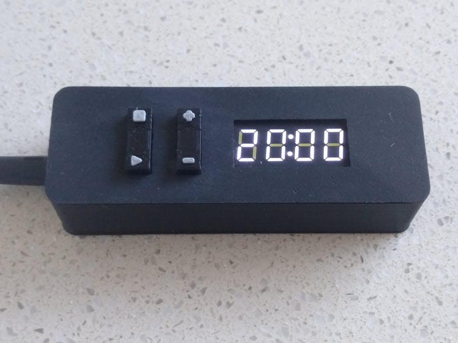
In todays world of Apps for your smart phone, a countdown timer might seem like a bit of a redundant build considering the prolific amount of free timer Apps. As a project, this was a interesting build.
VideoMicroprocessorI chose to use a cheap ATtiny1614 processor to drive a 4-Digit 7-Segment clock display. As the ATtiny1614 is a 14 pin device, it became a challenge to connect the 11 pins of the display, 4 switches and a buzzer to the 11 available IO pins (ignoring reprogramming the RESET/UPDI pin as another IO pin).
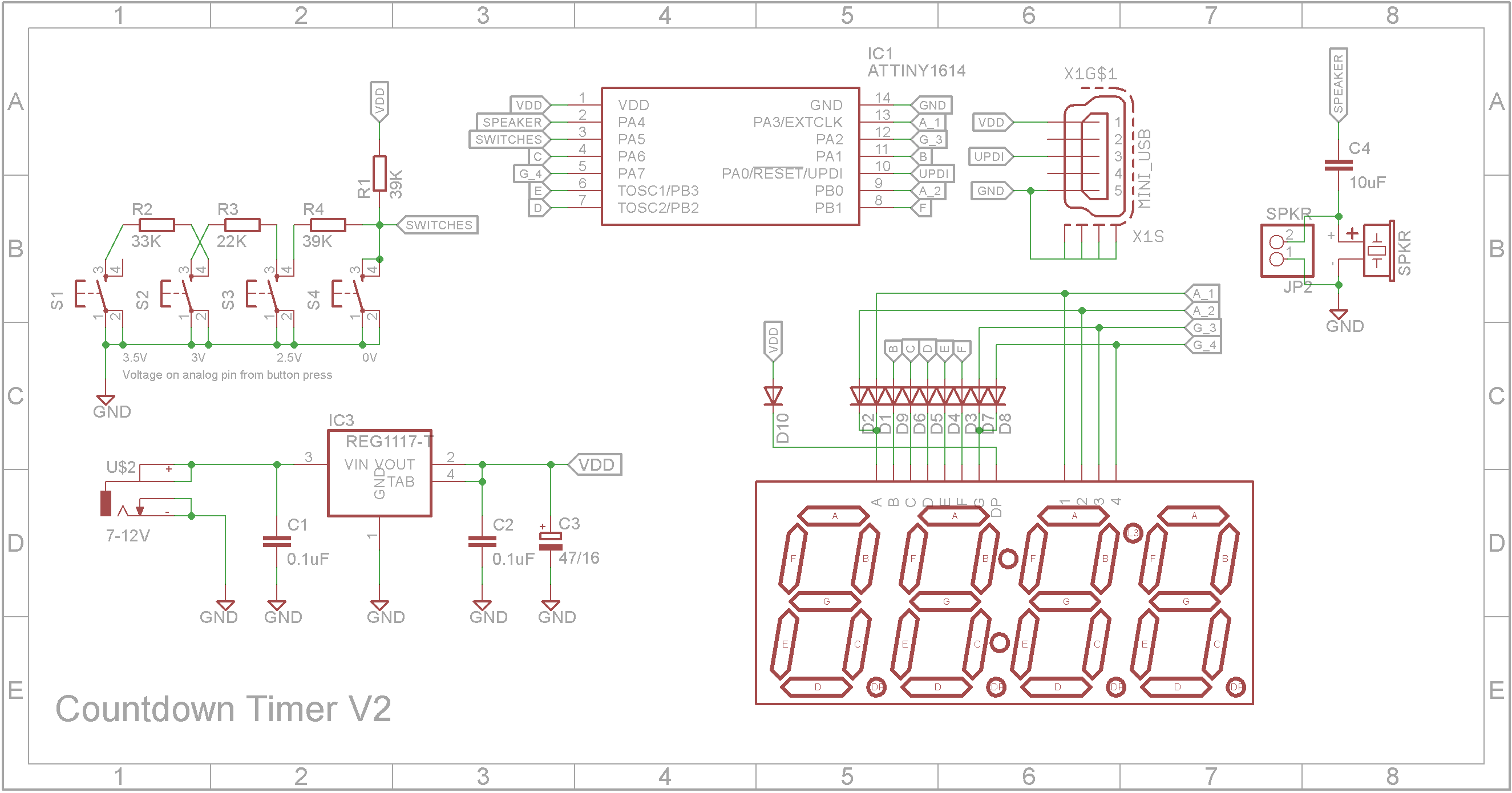
The switches form a voltage divider and is read as an analog input allowing all switches to use a single IO pin. The buzzer also uses a IO pin. This left 9 pins to connect to the 11 pins of the display. I achieved this using a technique called charlieplexing.
CharlieplexingThis technique uses the fact that an IO pin can have 3 states (HIGH, LOW and INPUT). When a IO pin is configured as an INPUT it is in effect disconnected from the circuit.
Consider the following circuit where 6 LEDs are driven by 3 IO pins.
Now each pin can be either a INPUT, OUTPUT HIGH or OUTPUT LOW. By manipulating these, you can address each LED individually.
Charlieplexing allows n pins to control (n*n − n) LEDs. However this technique is not without its problems. In practice each IO pin has a resistor to provide a sufficient voltage drop so as to limit the current through the lighted LED.
MultiplexingA 7-Segment display has 7 individual segments or 8 if you count the decimal point. If all the cathodes of each segment LED is connected together (common cathode), 9 pins are required (7 for the anode segment LEDs, 1 for the anode decimal point LED and one for the common pin for all the connected cathodes). When multiple digits are present, rather than having 9 pins for each digit, all the anodes on each digit are connected.
Assume you connect all pins to a microprocessor. To control each digit in the display, you need configure the processor to hold the common cathode pin of digit 1 LOW and the common cathode pins of the other digits HIGH while setting the segments for digit 1 HIGH for those segments you want to light up.
Next apply LOW to the CC pin of digit 2 and set the other digits CC pin HIGH while setting the segments for digit 2 HIGH for those segments you want to light up.
This repeats for each digit in turn and keeps repeating over and over again. If the speed is fast enough, persistence of vision means the lighted segments appear as being constantly lit.
NOTE: All PN junctions such as those in each LED segment have a small capacitance. This can take a while to discharge when power is removed. This means the segment may stay partially lit even when it is not being addressed. This is called ghosting and can be a problem with multiplexing especially when charlieplexing is used as well. It can be solved by driving the currently lit segments off before lighting up the next set of segments.
Mixing Charlieplexing and MultiplexingTo have a 4-Digit 7-Segment display controlled using 9 IO pins, the digit pins are charlieplexed with two of the segment pins.
Segment A is charlieplexed with digits 1 & 2.
Segment G is charlieplexed with digits 3 & 4 and operates in the same manner.
Final SchematicThe final system can be powered either by a 7-12V power brick or via the 5V USB Mini socket (which also allows programming via a UPDI programmer). The buzzer is DC isolated with a 10uF ceramic capacitor. The colon LEDs on the display are permanently on.
The STL files are included. Either take these to a 3D print shop or if you have your own printer, run them through your slicing software. I used a 0.2mm layer height with no supports.
The "Button_Tops.stl" can be printed in two colors. Slice using an 0.2mm layer height and change the filament at the start of layer 28 to a contrasting color to make the button top symbols stand out.
On the front panel, drill out the four PCB mounting holes with a 2.5mm drill and create a thread with a 3mm tap.
Make sure the top fits snugly onto the bottom. You might need to do some filing if it is too tight.
The PCBAs the ATtiny1614 microprocessor only comes as a Surface Mount Device (SMD), I decided to use SMD packages for most of the components in the build.
The Eagle files have been included should you wish to have the board commercially made or you can do as I did and make them yourself. I used the Toner method.
Assembly - Step 1Start by adding the SMD components. I find it easier to use solder paste rather than use solder from a reel when soldering SMD components.
Add the links if your board is single sided.
Add the top-side components.
If your board is double sided with through-hole plating, you can mount the speaker on the underside of the board and solder it to the top-side. For single sided boards, you need to solder two wires to the speaker pins and solder them to the two holes provided.
Drill out the mount holes on the case top with a 2.5mm drill and create a thread with a 3mm tap. Insert the two button tops into their respective holes on the case top and screw the board onto its mounts using four 6mm M3 screws.
The ATtiny1614 is part of the new breed of ATtiny microprocessors. Unlike the earlier series such as the ATtiny85, the new breed use the RESET pin to program the CPU. To program it you need a UPDI programmer. I made one using a Arduino Nano. You can find complete build instructions at Create Your Own UPDI Programmer. It also contains the instructions for adding the megaTinyCore boards to your IDE.
The USB socket provides power to the Countdown Timer (5V). The UPDI pin of the ATtiny1614 processor is connected the D+ pin on the USB socket. This allows the programming of the ATtiny1614 using a custom cable. USB Mini plugs are available on eBay or you can cutup an old USB Mini cable.
Once the board has been installed in the IDE, select it from the Tools menu.
Select Board, chip, clock speed and the COM port that the Arduino Nano is connected to.
The Programmer needs to be set to jtag2updi (megaTinyCore).
Open the sketch and upload it to the ATtiny1614.
Software DesignBy not using a LED driver IC like the MAX7219, it means all the hard work has to be done in software. After I got the display running, I found it was way too bright. To reduce the brightness, I used a technique called Bit Angle Modulation (BAM) which I won't go into here but just to say it adds to the complexity of the code. The BAM encoding provides 16 levels of brightness.
The Countdown time is counted down by the in-built RTC in the ATtiny1614. This fires an interrupt every second. An interrupt service routine decrements the counter and sets a flag to let the foreground loop know when to update the display.
When the time expires, a melody from a random set of melodies is played. This is done using the standard tone library. Because the tone library requires all the CPU cycles, the display is disabled while the music plays. The SWITCHES pin is configured as a digital input with a pin change interrupt so as to break into any melody playing. This causes the music to stop. The display is enabled and the SWITCHES pin is reconfigured as an analog input.
ConclusionThis was a challenging build in both terms of designing the hardware and software. In hindsight, I probably should of used a MAX7219 LED driver.


Comments
Please log in or sign up to comment.