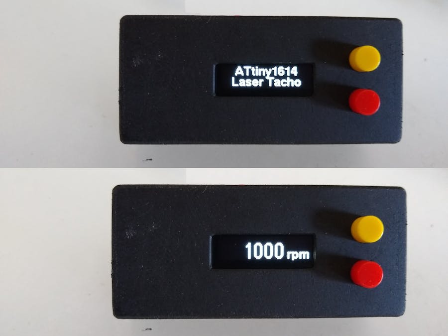
This Laser Tachometer is a rebuild of Elite Worm's Build a Laser Tachometer. Both the hardware and software have be redesigned.
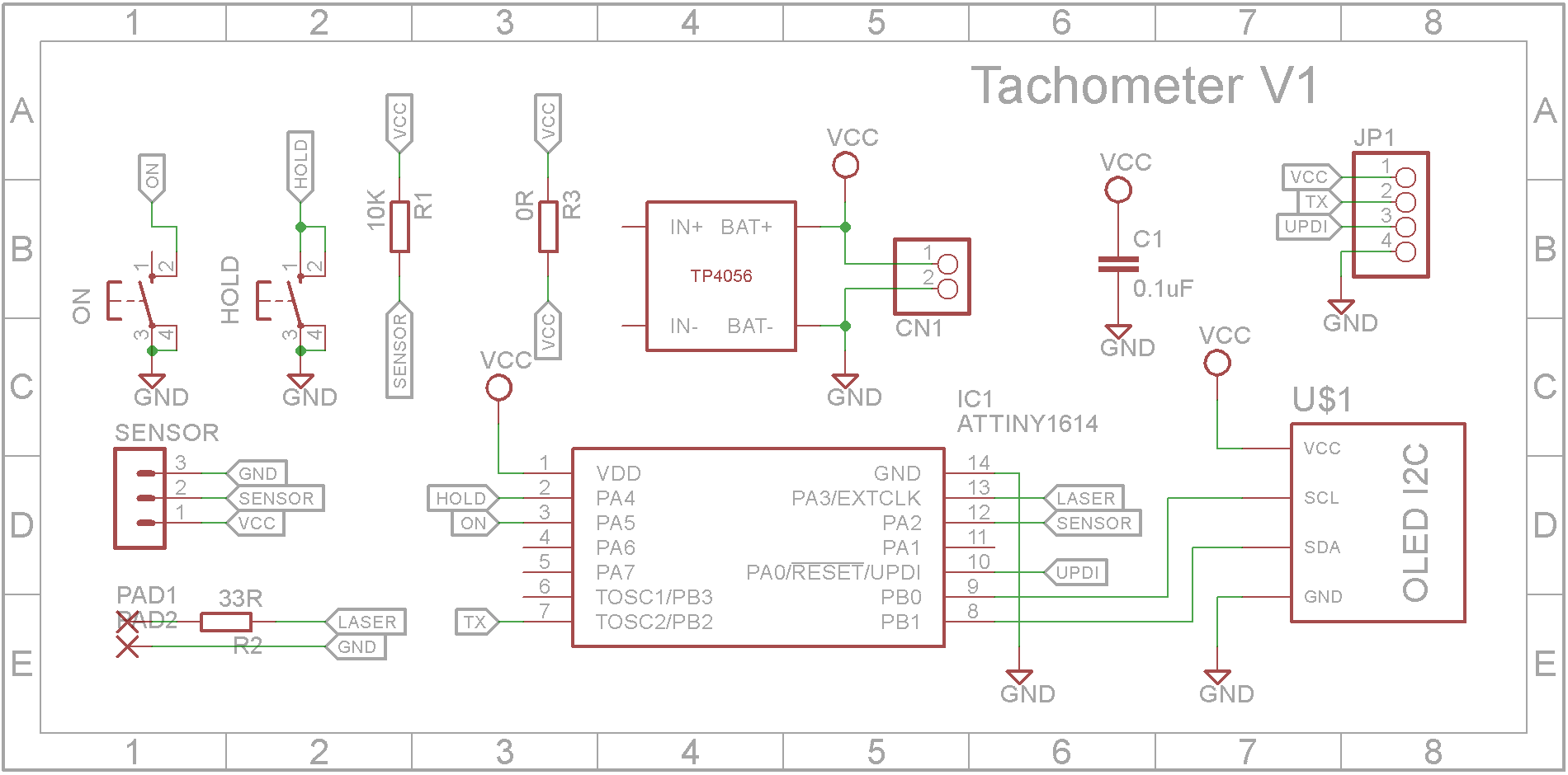
Hardware designThe original version by Elite Worm used a Arduino Nano. I decided to replace it with a ATtiny1614 microprocessor. This processor has a very low power consumption in sleep mode. The redesign is powered by a 3.7V Li-on battery and includes a TP4056 charger module to charge the battery.
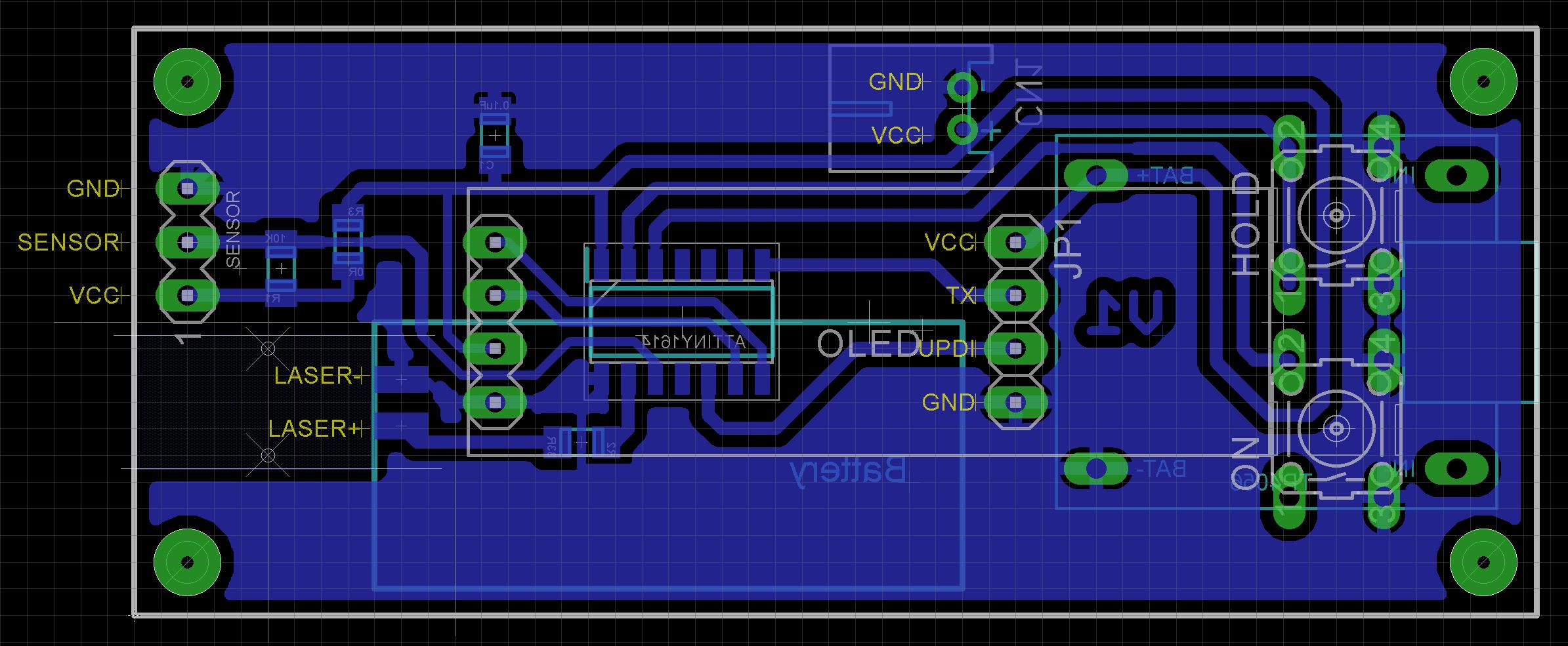
I made a custom PCB to hold the microprocessor and associated connections.
I bought a KY-008 laser and sensor kit from Ali-Express. After testing it, I only ended up using the sensor. As the laser in the kit was already mounted on its own PCB, I decided to use a separate 5mW laser that I had lying around.
Note that the 5mW laser unit has a 33 ohm resistor between the negative pin and blue negative supply wire. This is removed. A piece of tinned copper wire is soldered to both pads and bent at right angles to then be soldered to the PCB.
The case is 3D printed using a 0.2mm layer height. Open the STL files in your slicer software or if you don't have a 3D printer, provide them to your local print shop. Supports are not necessary.
The Eagle files are included in case you want to get the board commercially made or you can make it yourself. I used the Toner method to make mine.
Start by adding the SMD components to the board. I find it easier to use solder paste rather than use solder from a reel when soldering SMD components.
Add the 4 pin header for the programmer and 4 individual pin headers that the TP4056 charger module will be soldered on to. Also add the JST battery socket.
Using Super Glue, glue the button tops onto the buttons. Do not let the glue run down the shaft and into the switch. Solder the two buttons onto the PCB.
Add glue some packing near the buttons for the display to sit on. I used a old pin header with the pins removed as it will match the height of the pin header on the OLED display. Finally add the OLED display module.
Solder on the TP4056 module to the pins you added earlier.
Next add the laser module. The images below show you how it is mounted.
Next add the sensor. Bend the leads as shown below.
Prepare the case by creating a thread in each PCB mount with a 3mm tap. Screw the PCB into the case using four 6mm M3 screws.
Unlike the earlier ATtiny series such as the ATtiny85, the ATtiny1614 uses the RESET pin to program the CPU. To program it you need a UPDI programmer. I made one using a Arduino Nano. You can find complete build instructions at Create Your Own UPDI Programmer. It also contains the instructions for adding the megaTinyCore boards to your IDE.
All the components are 5V tolerant so provided the battery is not present, you can power it from the UPDI programmer. If the battery is installed, just connect the GND and UPDI wires and leave off the VCC wire.
Once the board has been installed in the IDE, select it from the Tools menu.
Select the ATtiny1614 board in your IDE
Select Board, Chip, Clock speed, and the COM port that the Arduino Nano is connected to.
The Programmer needs to be set to jtag2updi (megaTinyCore).
Open the sketch and upload it to the ATtiny1614.
Using the tachometerIt's important the the surface you shine the laser on will reflect the light back to the sensor. When measuring the speed of my drill, I taped some white reflective paper to the chuck so that the sensor will pick up the change in contrast from the black metal.
To turn the unit on, press the RED button. A splash screen is displayed for 3 seconds and the screen will then display "Ready". Pressing the YELLOW button will turn on the laser and the unit will show the speed of the object that the laser is pointed to. Releasing the YELLOW button will switch off the laser and lock the display to the last value shown. The unit powers off after 20 seconds or when you press the RED button again.
ConclusionThanks Elite Worm for a delightful project. I'm not sure that I actually have a use for it but it was a fun build in any event. 👍👍👍


Comments