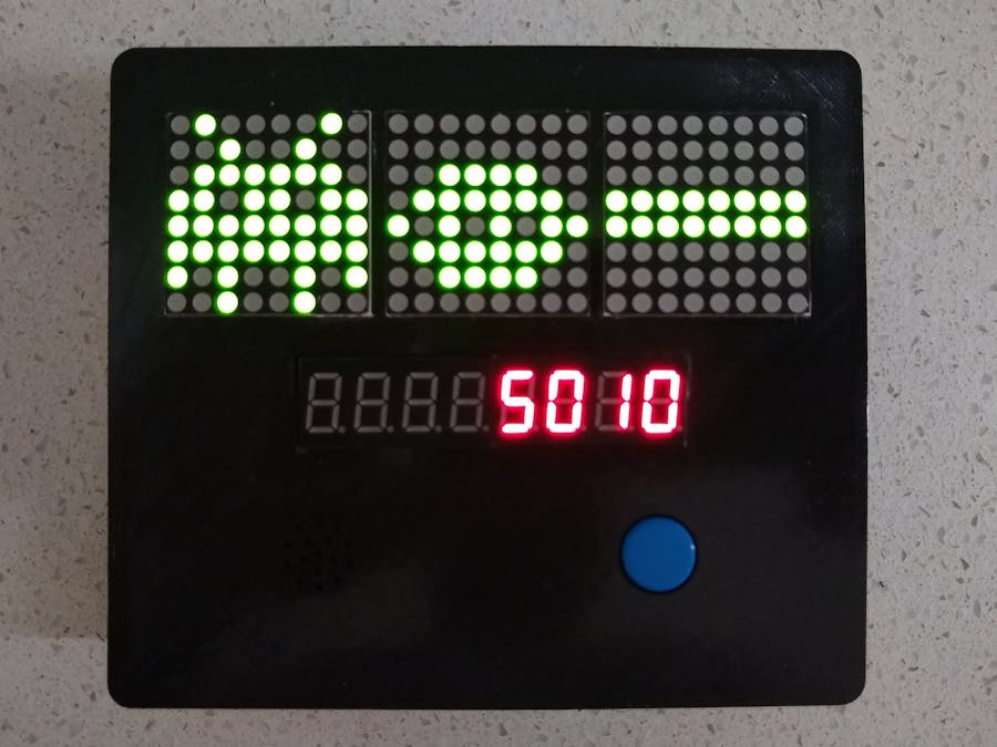
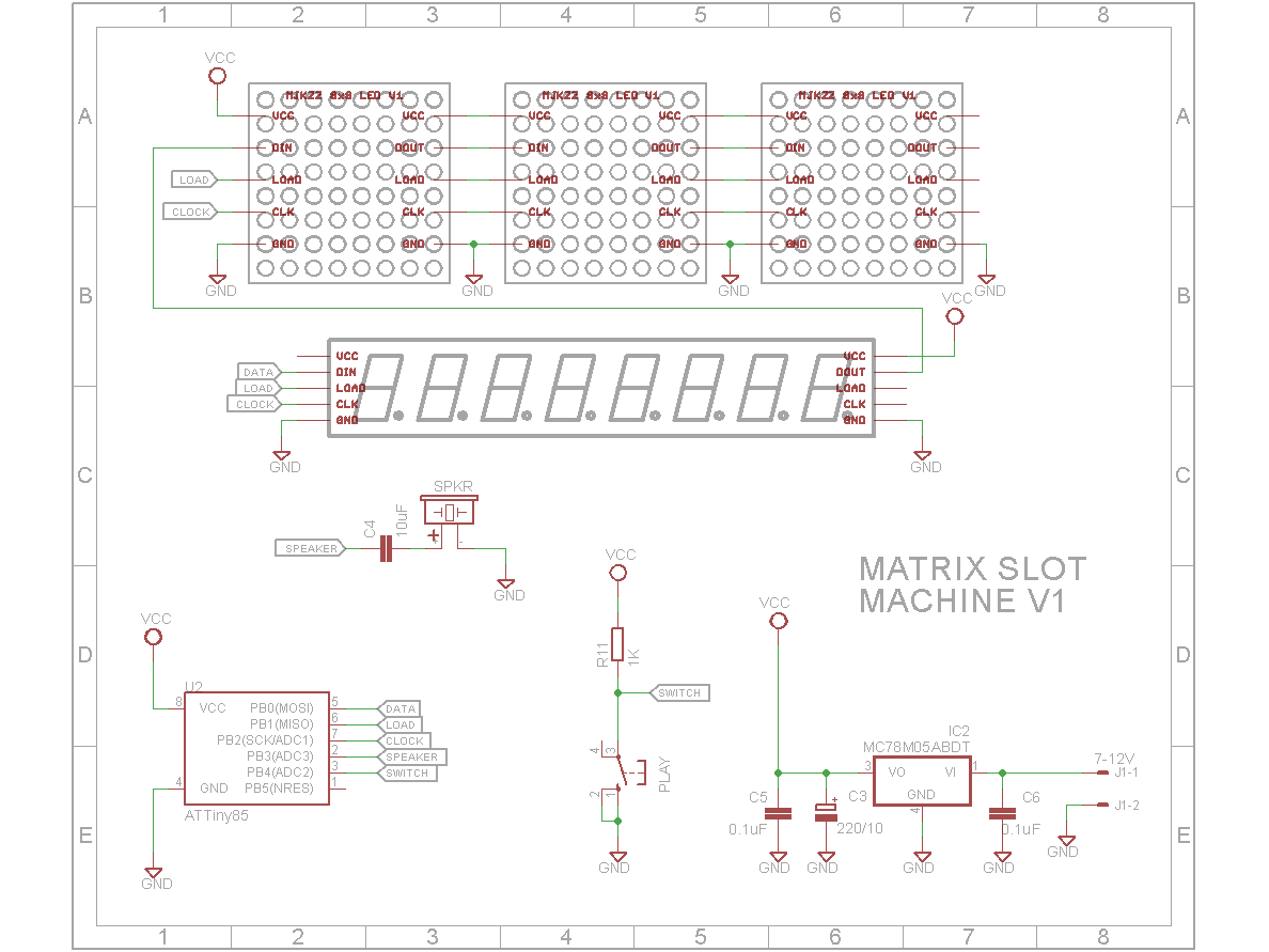
A while ago, I was looking at the Arduino Slot Machine by seawarrior181. It seemed a good project to modify and try to get it to run on an ATtiny85 microprocessor. I decided not to include the 4 line LCD display because the statistics wasn’t my primary goal. (It still calculates and stores all the statistics that seawarrior181’s version has, it just doesn’t display them). Also I did away with multiple buttons. It means that the players bet is fixed and is the same on every spin (much like a real slot machine).
VideoSoftwareI kept the sound and payout routines and re-wrote the rest of the code. My final version uses 6850 bytes Flash (83% on an ATtiny85) and 196 bytes SRAM (38%) giving 316 bytes of stack space.
To achieve this, the reel symbols have been moved to Flash memory, variables have been reduced to 8 bit where it was appropriate to do so and the code footprint reduced by more efficient coding.
Developing the gameI developed the software on an Ardunio UNO because at the time I started, it wasn’t certain that everything would fit into an ATtiny85.
In the breadboard version I used a 4 x MAX7219 8x8 matrix board because it didn’t require extra wiring between digits. The final version uses 3 single MAX7219 8x8 matrix boards so that there is a gap between each reel.
The software has the following compiler constants:
#define DIGITS 5 //Number of MAX7219 daisy chained
#define WHEELS 3 //Number of wheels on machine
#define MONEY 0 //Location of 8 Digit 7 Segment display in MAX7219 daisy chain
If you are using a 4 x matrix board and a 8-digit 7-segment display, that means 5 MAX7219 ICs are daisy changed together. Set DIGITS to 5 in this case.
Although the payouts all assume three reels, the code to spin the wheels is designed for any number of wheels. The WHEELS constant tells the spin code how many wheels it should emulate.
The 8-digit 7-segment display can be wired between the Arduino and matrix displays or after the matrix displays. If it is the former, set the MONEY constant to 0 reflecting that it is on the first MAX7219 IC encountered.
The software assumes that the first reel is on the far left and the last reel is on the far right. On a 4 x MAX7219 8x8 matrix board the first matrix is on the far right. To tell the software this, you need to define a macro called DIGIT that will convert the logical position to the physical position.
Logically the software considers matrix 0 the left one, matrix 1 the middle one and matrix 2 the right one. If using a 4 x MAX7219 8x8 matrix board, you would redefine the DIGIT macro as:
#define DIGIT(a) (WHEELS - a)
so a logical 0 = physical 3, logical 1 = physical 2, logical 2 = physical 1 (physical 0 being the 8-digit 7-segment display)
Programming the ATtiny85The problem with using the Digispark system for programming ATtiny85 processors is that the Digispark boot loader uses a big chunk of Flash memory leaving only around 6800 bytes from the 8192 bytes. However, the boot-loader is there really only to support serial communication via the USB port. If this isn’t required, the boot-loader doesn’t even need to be there.
So the ATiny85 is programmed using an USBtinyISP programmer. I used my own AVR ISP programmer.
Use the following fuses
avrdude -c usbtiny -p t85 -U lfuse:w:0xe1:m
avrdude -c usbtiny -p t85 -U hfuse:w:0xdd:m
avrdude -c usbtiny -p t85 -U efuse:w:0xfe:m
This will turn off the prescaler and enables the PLL so the chip can run at 16MHz.
In the Arduino IDE, add the following package in File-Preferences-Settings-Additional Board Manager URLs
http://drazzy.com/package_drazzy.com_index.json
Now select the following from the Tools menu
- Board: “ATtiny25/45/85”
- Chip: “ATtiny85”
- Clock: “16MHz (PLL)”
- Programmer: USBtinyISP
Open the sketch and uncomment the #define ATtiny85 on line 9 and ensure #define DEBUG is commented out. Select Sketch-Upload using programmer to upload the sketch to the ATtiny85.
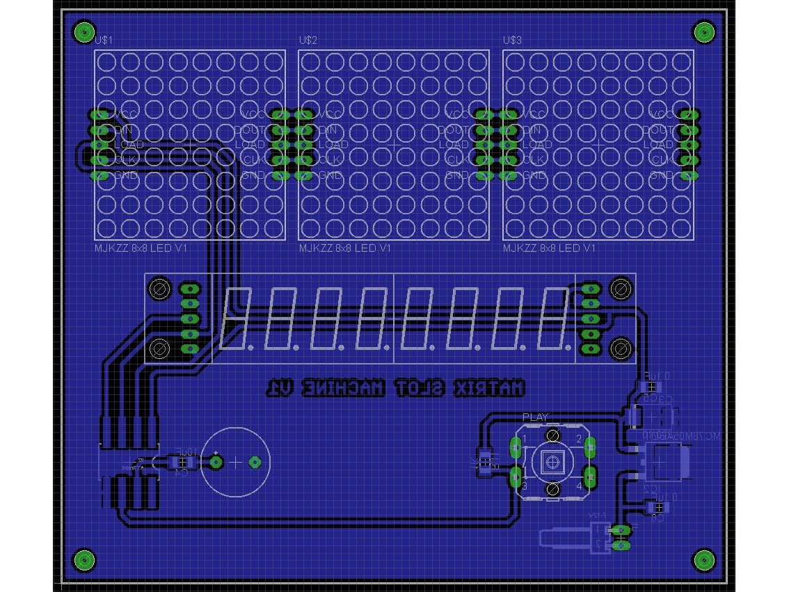
Building the gameI designed a PCB to hold the components and 3D printed a suitable case. The ATtiny85 chip is mounted on the back of the board. I used a 8 pin DIL variant. The IC socket has its pins flattened out and soldered to the board like a SMD device. There is also a 5V SMD regulator.
I have included the Eagle files in case you want to get the board commercially made or do as I did and make it yourself. I used the Toner method.
After 3D printing the case, drill out the mount holes with a 2.5mm drill and create a thread with a 3mm tap. Use 6mm M3 screws to hold the board in place.
Wire up the battery and switch
The only issue I had with this build was the variation in some of the components. It seems not all the matrix modules and 8-digit 7-segment displays have the same pinouts or sizes.
If seawarrior181 got his formulas right and this is a true reflection of how payouts work in a real casino, I don’t know why anyone would want to play these machines.
You might lose a few hairs building it, but at least you won’t lose your shirt playing it 😁😃👍


Comments
Please log in or sign up to comment.