


Hardware components | ||||||
| × | 1 | ||||
| × | 1 | ||||
 |
| × | 1 | |||
| × | 1 | ||||
| × | 1 | ||||
 |
| × | 1 | |||
| × | 1 | ||||
| × | 1 | ||||
| × | 1 | ||||
 |
| × | 1 | |||
| × | 1 | ||||
Software apps and online services | ||||||
 |
| |||||
Hand tools and fabrication machines | ||||||
 |
| |||||
 |
| |||||
This project is a version of the NOTUA NV-FS1 Fan on steroids.
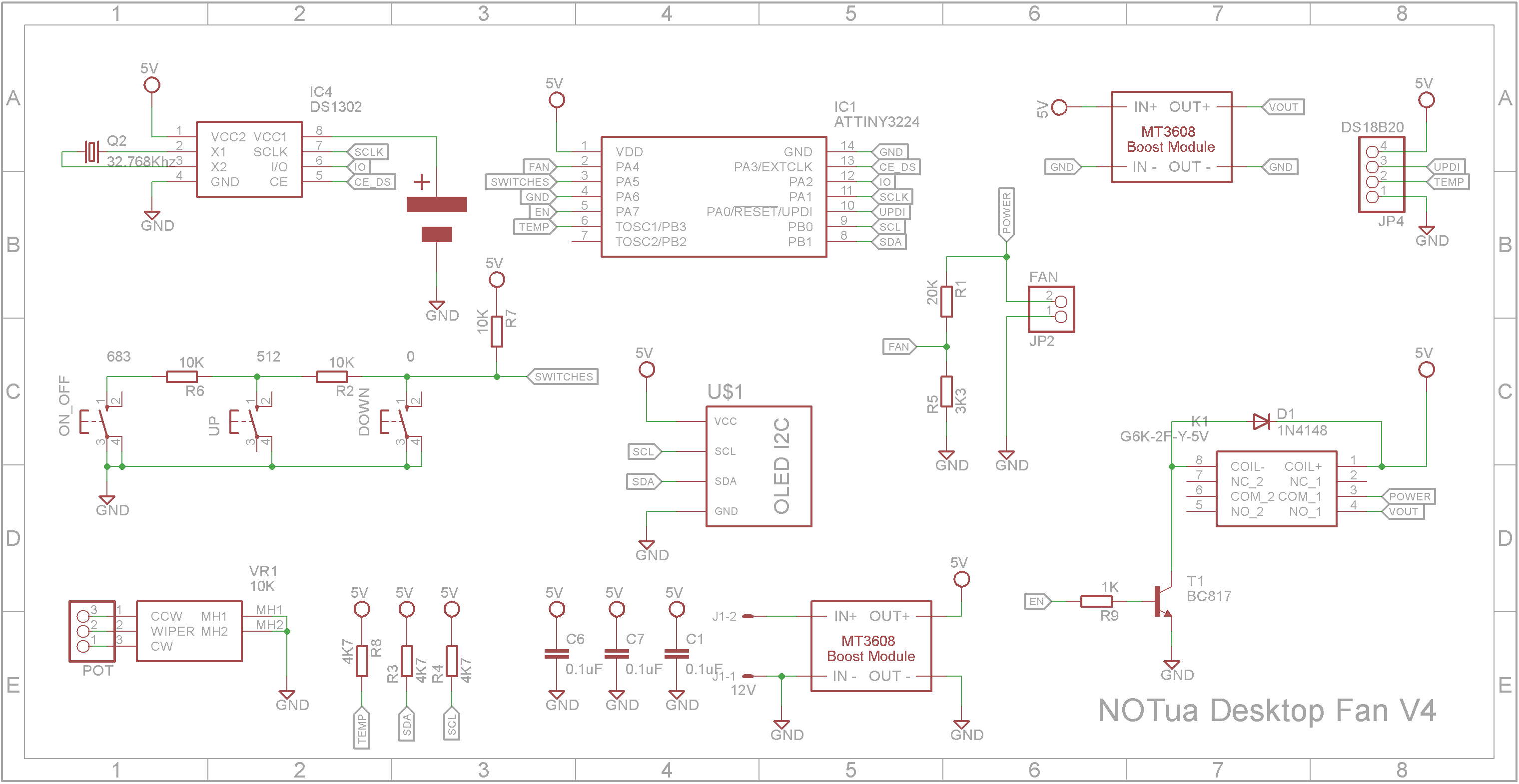
The base of the fan has a built-in real-time clock, fan speed control (displayed as a percentage) and it also displays the current temperature. It is powered from a standard 12V 1A power brick.
Demonstration3D printingAll 3D printing is done using a 0.2mm layer height. You will need to print 2 of "Fan - M6 V2.stl", "Fan - Leg.stl" and "Fan - Bracket V2.stl"
When printing "FAN - Text.stl", switch to a contrasting color at the start of layer 4. Use double-sided tape or glue to join "FAN - Text.stl" to "FAN - Front.stl".
After printing "Fan - Box.stl", heat insert M4x4x5 brass inserts into the holes that the legs are screwed to using M4x8mm black round head screws.
DesignVersion 1 of this project used PWM to control the fan. This was a complete failure as even with PWM around 5%, the fan showed no considerable loss of speed due to the inertia of the fan blades and the low friction bearings.
Version 2 was changed to use the XL6009 Boost Convertor allowing the fan voltage to vary from 4V to 19V from a 5V power supply. The problem with this solution was the fan couldn't switch off because 4V was enough to keep the fan spinning.
Version 3 was changed to control the enable pin on the XL6009 Boost Convertor so it could be switched off via the microprocessor. While it switched off the boost convertor, it didn't take the output voltage to zero. This is because the input has a direct path to the output.
Version 4 was updated to include a relay to switch on or off the output from the XL6009 Boost Convertor.
While building this project, I came across another XL6009 Boost Convertor that has multiple inductors. In this variant, the input is isolated from the output via a capacitor. This means when the XL6009 is disabled, the output should go to zero volts.
The footprint of this variant differs from the single inductor variant so I didn't try it out.
Modifying the XL6009 Boost ModuleThe XL6009 comes in a number of variants as shown below. This project used the center version.
The XL6009 needs some modifications for this project. The 10K trimpot needs to be removed and a 3-pin male header put in its place. Also the 1K 0603 resistor should be replaced with a 0603 680 ohm resistor.
The corner holes need to be drilled out with a 2mm drill to accommodate 4xM2 8mm brass stand-offs. I only had male-female stand-offs but female-female will work just as well.
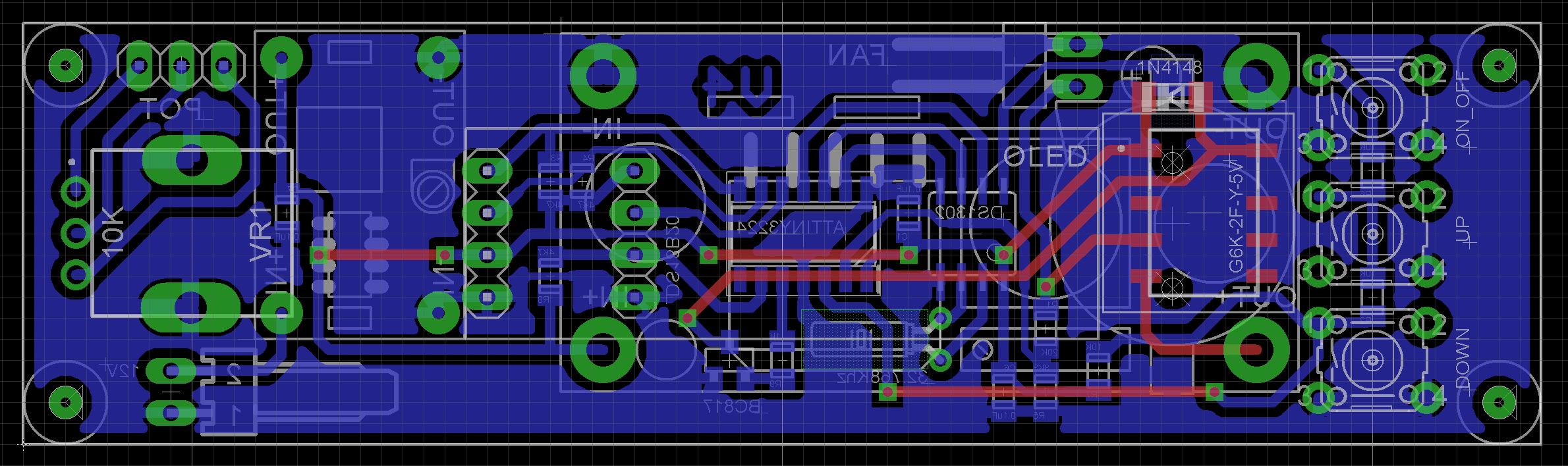
PCB DesignThe PCB is designed to be screwed onto the front of the case. The DC-DC Step-down module that supplies the primary power is fixed to the copper-side of the board. The XL6009 is also mounted on the copper side using M2x8mm brass stand-offs. These provide the electrical connection for the input and output to/from the boost module.
The Eagle files have been included should you wish to have the board commercially made or you can do as I did and make it yourself. I used the Toner method. (The board I made was single-sided so I glued the relay on and used wire -wrapping wire to wire it up).
Assembling the PCBStart by adding the SMD components. I find it easier to use solder paste rather than use solder from a reel when soldering SMD components. I used my SMD Hot Plate to reflow the solder paste.
Leave off the CR1220 battery holder for now.
Add the links if your board is single sided.
On the copper side of the PCB:
- Add the 3 pin header to connect to the XL6009 module.
- Add four 1 pin headers to mount the mini DC-DC step-down module.
- Add the four M2 8mm brass posts that the XL6009 module will be screwed to. Solder the base of the posts to the copper to make a good electrical connection.
(Ignore the blue 1 pin header. This was removed from the V4 PCB)
On the copper side of the PCB:
- Add a 2 pin male right angle header to connect the fan to.
- Add a KF2510 2 pin male right angle connector for the power
- Add the CR1220 Battery Holder
On the component side of the PCB:
- Glue on the two "Fan - Spacers.stl" to support the OLED display
Version 4 MODIFICATION: As previously mentioned, the version 4 modification added a relay to disconnect the power to the fan. The V4 board has pads on the component side for the relay and associated diode. My picture shows the V3 board with the relay glued on and wired up using wire-wrap wire.
Solder the relay and diode to the component side of the PCB.
On the component side of the PCB:
- Add the 32, 768Hz crystal.
- Add the RV09 10K potentiometer
- Add three 6mm x 6mm push button switches with a 13mm shaft
- Add the 128x32 OLED display
On the copper side of the PCB:
- Set the mini DC-DC step-down module to output 5V BEFORE soldering it onto the four 1-pin headers you added earlier.
- Solder on a 4-Pin male right-angle header that will be connected to the temperature sensor and also used to program the ATtiny3224 CPU. I tend to dab colored paint on my pin headers to show which pin is positive etc.
Now would be a good time to program the microcontroller. See programming section.
Screw the PCB to the front panel using four M2 4mm screws.
Screw the XL6009 module to the brass posts using four M2 4mm screws. Add the 3-pin female to female cable to connect the boost module to the PCB. (This was where the trimpot was).
I used 30mm screws and a chrome fan screen to secure the fan to the two side brackets.
The legs were held onto the box using M4 8mm black round-headed screws.
The DS18B20 was glued in the channel provided and a female pin header was added to the cable after it was cut to length.
The power socket is screwed in using M2 8mm screws.
Originally a DC panel connector was used to plug the fan into the base. However the plug stuck out too far for my liking so it was replaced with a KF2510 2-pin male/female connector. The male connecter is glued to the back of the case.
When wiring the front panel, you will need to temporarily remove the XL6009 boost module to plug in the cables. Once it is done the front panel should slide into the box. You may need to file some plastic away if it is too tight or add some masking tape around the inside of the base if it is too loose. It will depend on the accuracy of your 3D printer.
ProgrammingUnlike the earlier ATtiny series such as the ATtiny85, the ATtiny3224 uses the RESET pin to program the CPU. To program it you need a UPDI programmer. I made one using a Arduino Nano. You can find complete build instructions at Create Your Own UPDI Programmer. It also contains the instructions for adding the megaTinyCore boards to your IDE.
Once the board has been installed in the IDE, select it from the Tools menu.
Select the ATtiny3224 board in your IDE
Select Board, chip, clock speed, COM port the Arduino Nano is connected and the programmer
The Programmer needs to be set to jtag2updi (megaTinyCore).
Wire up the programmer to the PCB.
- GND to GND pin (Black)
- UPDI to UPDI pin (Grey paint)
- 5V to KF2510 positive pin (Red paint)
Open the sketch and upload it to the ATtiny3224.
ConclusionIt seems that a project you think would be so simple to design and build often turns out to be full of challenges. In the end, the fan works well and looks cool (excuse the pun) on any desktop.


Comments
Please log in or sign up to comment.