


Hardware components | ||||||
| × | 1 | ||||
| × | 1 | ||||
| × | 1 | ||||
 |
| × | 1 | |||
| × | 1 | ||||
| × | 1 | ||||
| × | 1 | ||||
| × | 1 | ||||
Software apps and online services | ||||||
 |
| |||||
Hand tools and fabrication machines | ||||||
 |
| |||||
 |
| |||||
A few years back, fellow Hackster Juraj published a Kitchen timer and clock which he built into a power brick. I liked this concept so I thought I would take this concept and apply a few improvements to it.
The power brickThe hardest part of this build if finding a suitable power brick. Looking through my box of power bricks I came across one that contained a simple transformer design rather than the more common switched mode power supply.
As the image shows, the bottom and top parts of the case were held together with four screws. Rather than drill and mill the top part to fit the components as Juraj did in his build, I decided to design and 3D print a top so that I could screw my PCB in place and not rely on glue.
3D PrintingThe STL files are attached. You can slice them with your slicing software or take them to be printed at a commercial 3D print shop.
"Timer - Box.stl" - 0.2mm layer height, no supports
"Timer - Clips.stl" - 0.2mm layer height, no supports
"Timer - Display.stl" - 0.1mm layer height, no supports
"Timer - Knob.stl" - 0.1mm layer height, no supports
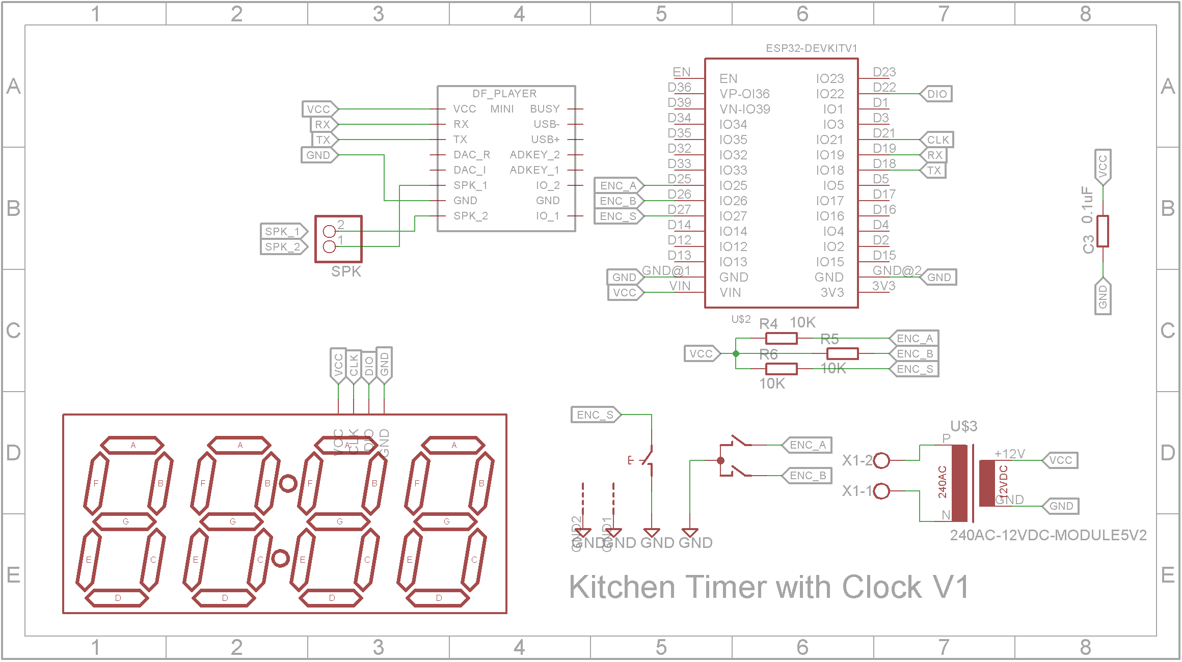
SchematicThe CPU is an ESP32. Being WiFi enabled, the clock obtains its time over the Internet from a time server. To improve the sounds that can be played, a DF mini MP3 player module is also included. This module requires a micro SD card and you will need to unzip the attached "mp3.zip" onto this SD card.
The Eagle files have been included should you wish to get the board commercially made or you can make it yourself. I used the Toner method to make mine.
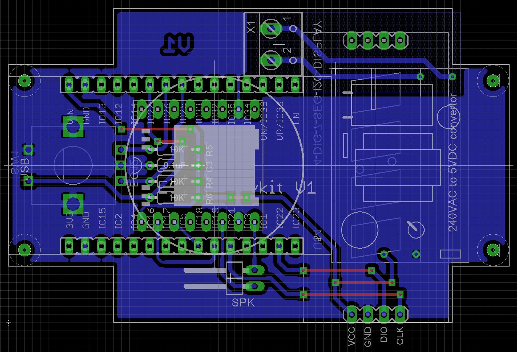
Add the links if your board is single sided.
Next add the headers. If your board has through hole plating, you can solder the wires directly to the board rather than use a connector. If you use a header on a single sided board, here is the method I use to add them.
Place header on PCB with longer pin side down, solder pins, push black plastic down towards the PCB.
Add the 3 x 10k 1/8W resistors and the 0.1uF axial monolithic ceramic capacitor
Add the 2-pin male right angle header for the speaker connection.
Add the 2 x 15 pin female straight headers for the ESP32 module to plug into.
Solder the 2-way barrier terminal block onto the board.
Unzip the "mp3.zip" onto a empty micro SD card (16 GB or less) and insert the card in the SD spot on the DF mini player module
Add the DF mini player module.
Add the 240VAC to 5VDC 700mA module to the board. These modules come with a variety of footprints. You may need to use tinned copper wire to connect it to the PCB as the holes may not line up exactly.
Glue "Timer - Display.stl" spacers to the copper side of the board and solder the display onto the pin headers you previously added.
Add the rotary encoder to the copper side of the board.
Add two wires to the speaker. Screw the speaker into the case using "Timer - Clips.stl" clips. They are held in place with 2 x 4mm M2 screws. Place a 2 way Dupont header on the other end of the speaker wires.
Screw the PCB into the case using 4 x 4mm M2 screws.
Solder the mains supply wires to the wall pins. When screwing the other end of the wires into the barrier terminal block, I strongly recommend using Ferrules when screwing in the cables. (See TO FERRULE OR NOT TO FERRULE).
Finally plug in the ESP32 development module.
You can now screw the cases together using 4 x 20mm M3 screws.
ProgrammingAlong with the sketch, there are four libraries that you will need to install into your Arduino IDE first.
Upload the software attached to the ESP32. I selected Node32s in the Arduino IDE.
Using the clockPressing the rotary encoder will switch between the following modes:
Show Time - Shows the current local time in either 24 hour or 12 hour format.
Timer - Turn the rotary encoder to set the time in 10 second intervals. Press the rotary encoder to start the timer. Sounds will play when the count down ends and it will automatically switch back to Show Time mode. Pressing the rotary encoder while the count down is running will stop the count down.
Time Format - The left two digits shows Tf. The right two digits will be either 12 or 24 showing the current time format. Turn the rotary encoder to change the time format.
Alarm State - The left digit shows the letter A. The right two digits show either on or oF showing whether the alarm is on or off respectively. Turn the rotary encoder to change the alarm state.
Alarm Hours - The left digits shows the letters Ah. The right two digits show a number between 0 and 23. Turn the rotary encoder to change the alarm hour. The alarm is always shown in 24 hour time format.
Alarm Minutes - The left digits shows the letters An. The right two digits show a number between 0 and 59. Turn the rotary encoder to change the alarm minute.
When the alarm is enabled and the alarm is triggered, the alarm will switch itself off after one minute or when the rotary encoder is pressed.
Volume - The left digits shows the letters vo. The right two digits show a number between 0 and 99. Turn the rotary encoder to change the volume level. A short sound is played each time you rotate the rotary encoder so you can hear how loud the sound is.
Brightness - The left digits shows the letters br. The right two digits show a number between 10 and 90. Turn the rotary encoder to change the brightness level. The display is updated instantly so you can see the brightness level as you change it.
ConclusionThis is a very useful addition to my kitchen. It loudness and distinctive noise allows me to hear it from the other side of the house.


Comments