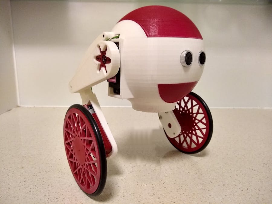
This is my make of Robot Axis V1 by Axioma Robotics and published on Thingiverse. I am still working on the software for this project. The hardware side is complete and since Axioma Robotics has designed this project as an educational project for software development, I decided to publish this anyway in case anyone wants to start building this variant.
Wheel motors & Thigh servosI used all metal gear 6V motors. I had to redesign the wheels to provide a tight fit on the motor shaft. It also allows for a M3 screw to fix the wheel to the shaft. Due to the tightness of the hub on the motor shaft, I found that the screws were unnecessary. The wheels are designed to take a 100m OD, 6mm CS O-ring as tires. All the parts were sourced from Ali-Express.
I disassembled the motors and spray painted the shells, wheels and 6-legged servo horns with gloss red paint.
When I screwed the thigh to the servo using the 6-legged servo horn, I found the leg to be quite loose (A lot of lateral play). To fix this the 3D printed shims can be used to pack out the servo horn to get a tight fit. I made 5 different pairs of shims ranging in thickness from 1.0mm to 1.8mm. Just pick the best pair that gives a tight fit.
Joints (Bearings)The joints of the robot used 3mm and 4mm brass tubes obtained from a hobby shop.
Two 3mm brass rods are fixed to each end of the shock absorbers. If they are loose, glue them in with super glue. The holes on the body and calf have 4mm inserts so that the 3mm brass rods can rotate freely.
A 3mm brass rod is fixed to the thigh and the calf contains a 4mm insert.
When cutting the brass tubes to size, leave enough length to fit the 3D printed pipe stoppers. Also make sure you clean off any burr that was left over from the cutting of the pipe. The 3mm rods should easily rotate inside the 4mm rods.
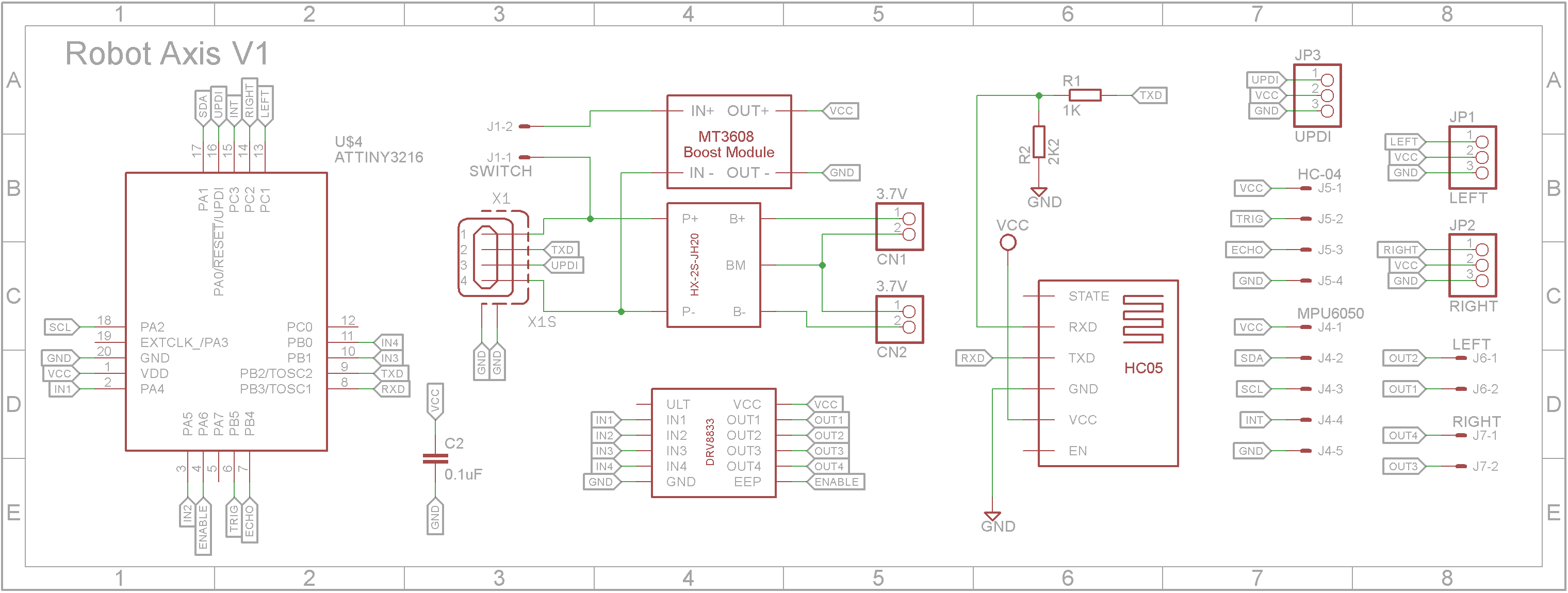
I designed the circuit around a ATtiny3216 microprocessor. (Sourced from Element-14). It has 32K of Flash memory and 2K of RAM. You can also use the newer ATtiny3226 microprocessor which has 3K of RAM as it is pin-for-pin compatible.
The robot runs on two 3.7V 1100mAh Li-Polymer batteries in series. To charge the batteries while they are in series, a battery balancing module is used to protect the batteries. I decided to use a USB Type B socket to charge and program the robot as these are very robust and can take a lot of punishment. The USB socket can not only take the 8.4V to 9V needed to charge the batteries but also has it's D+ line connected to the UPDI programming pin of the ATtiny3216. I also added the TX line to the D- line for debugging should that be necessary.
The bulk of the Robot uses off-the-shelf modules that you can obtain from sites like eBay, Ali-Express, Banggood etc. With the 5V regulator, make sure you set the output voltage to 5V before you add it to the PCB.
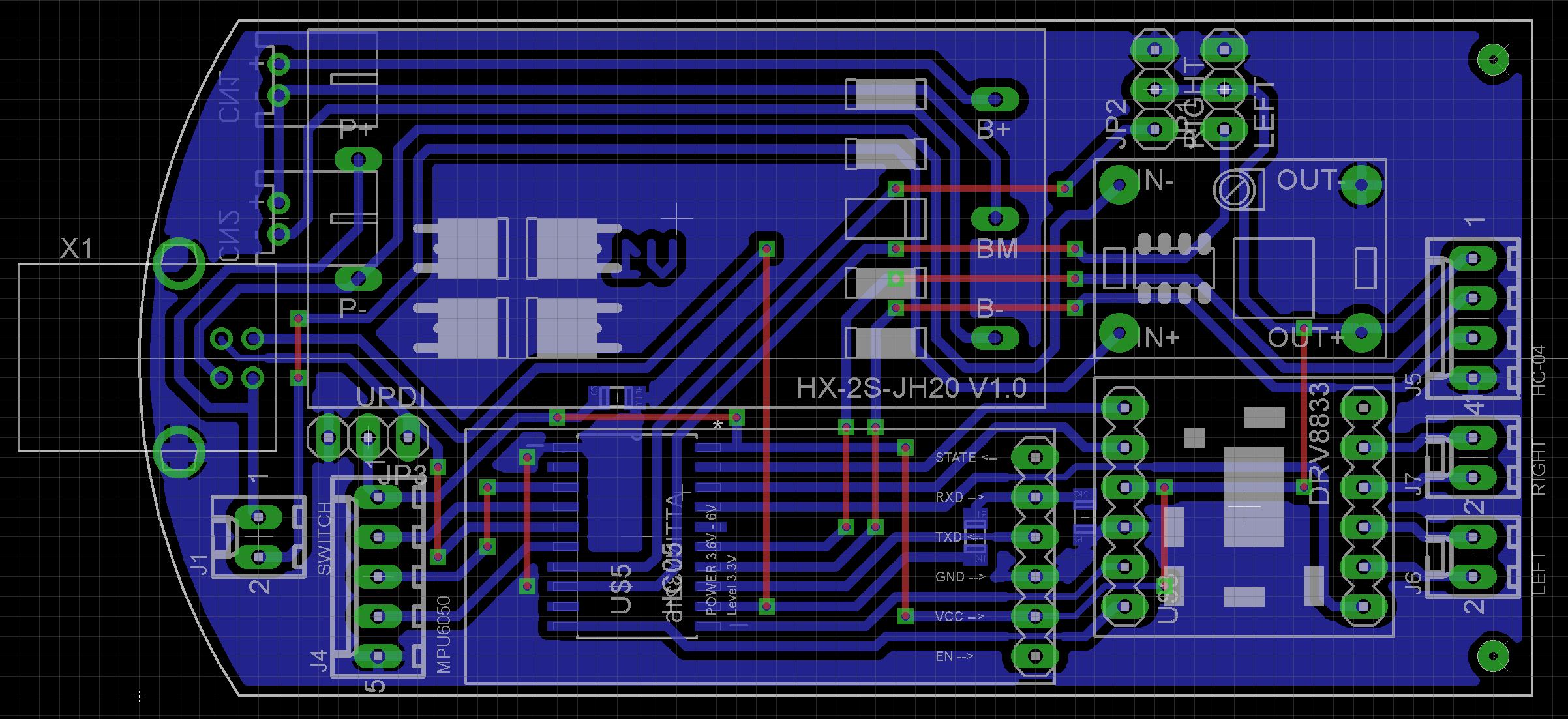
The Eagle files have been included should you wish to have the board commercially made or you can do as I did and make it yourself. I used the Toner method.
Assembly - ElectronicsStart by adding the SMD components. I find it easier to use solder paste rather than use solder from a reel when soldering SMD components.
Add the links if your PCB is single-sided.
Add the two JST sockets for the batteries to the copper size.
Add the modules and connectors to the component side.
3D print the Insert and super glue it into the body.
Next wire up the MPU6050 3 Axis Gyroscope & Accelerometer module and place it into the base. Add some foam packing to hold it in place. I used some foam pallets that are typically used when packing items for shipping.
Add the two 3.7V 1100mAh Li-Polymer batteries and plug into the PCB.
You are going to need to enlarge the USB hole so that the board will sit flat. (See picture). Add some more foam packing between the batteries and PCB before screwing the board in place using two M2 4mm screws.
Finally add the legs and plug in all the connections.
Unlike the earlier ATtiny series such as the ATtiny85, the ATtiny3216 uses the RESET pin to program the CPU. To program it you need a UPDI programmer. I made one using a Arduino Nano. You can find complete build instructions at Create Your Own UPDI Programmer. It also contains the instructions for adding the megaTinyCore boards to your IDE.
Just connect the GND and UPDI wires and leave off the VCC wire. Power the ATtiny3216 via the battery by turning on the Robot. You can either program it using the 3-pin header next to the USB port by removing the robot's hat or use the USB port with a cable were the ATtiny3216 UPDI pin is connected to the D+ pin.
ConclusionI hope those who are intending to build this robot find this useful. A special thanks to Axioma Robotics for a fantastic design and making the it public so we can all share in the fun of building it.


Comments