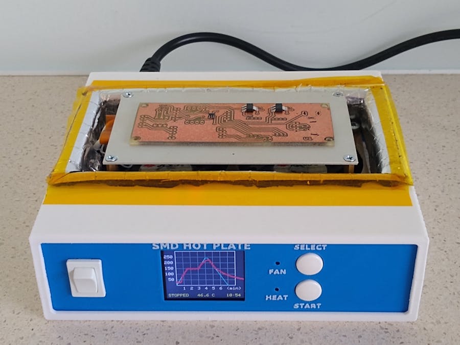
About 6 months ago, I built a SMD hot plate using a standard 200W element (See SMD Reflow Hot Plate). Although I use it wherever possible, its small hot plate limits the size of the PCB that can be reflow soldered. This new version uses a 400W hot plate and doubles the size of the heating area. To overcome the shortfall of my previous version, mainly in the area of cooling, this latest version has two 70mm x 70mm case fans mounted under the heating element and these provide a noticeable improvement in the cooling of the hot plate.
What are heating profilesThe issue with heating up Surface Mount Devices (SMD) is that if heated or cooled too quickly, potentially damage can occur to the device. Also the flux in the solder needs time to activate and any water vapor that may of seeped in needs time to evaporate. This usually requires a soak period for around 90 seconds at 150 degrees Celsius before raising the temperature to around 220 degrees Celsius to melt the solder paste. Thus manufacturers of these components provide heat profiles which you can sometimes obtain from their respective datasheet.
The main change I made in the design of the case was to mount the cooling fans below the hot plate so that air is forced up and around the hot plate.
The two 70mm x 70mm case fans are screwed to the base using M4 screws. I used a piece of single-sided PCB board to mount the 20mm posts that the hot plate is screwed onto.
Use the template attached to cut the copper-clad fiberglass FR4 board to size and to drill the required holes.
Originally I added the 100k ohm NTC 3950 Thermistor (also from AliExpress) in the hole where the element is and held it in place with Kapon high temperature tape. After testing I found that it performed better if it was just fixed to the middle of the underside of the hot plate using Kapon tape.
Finally I countersunk the holes so that if the PCB that is being heated is larger than the heating plate, the screw heads won't lift the PCB off the surface.
Next heat insulation material is used to cover the hole in the top of the case. I used "Car Soundproofing Deadening Mat Heat Sound Insulation Cotton Firewall Auto Hood Door Deadener 25x50cm 5mm Foam" from Ali-Express. (About AU2.80).
I also added some Kapon tape to tidy up the edges.
The rest of the case follows a clam shell design. The lugs on the clam shell can sometimes split on a 3D printed layer line when the screw is inserted. To protect against this, super glue a nylon washer to each lug.
3D printingAll printing is done using a 0.2mm layer height with no supports. The top, front, text and back pieces will need rotating on the built plate before slicing.
The first 3 layers of "400 - Text.stl" is printed using the front base color and switches to a contrasting color at the start of layer 4. Join "400 - Text.stl" to "400 - Front.stl" using double-sided tape.
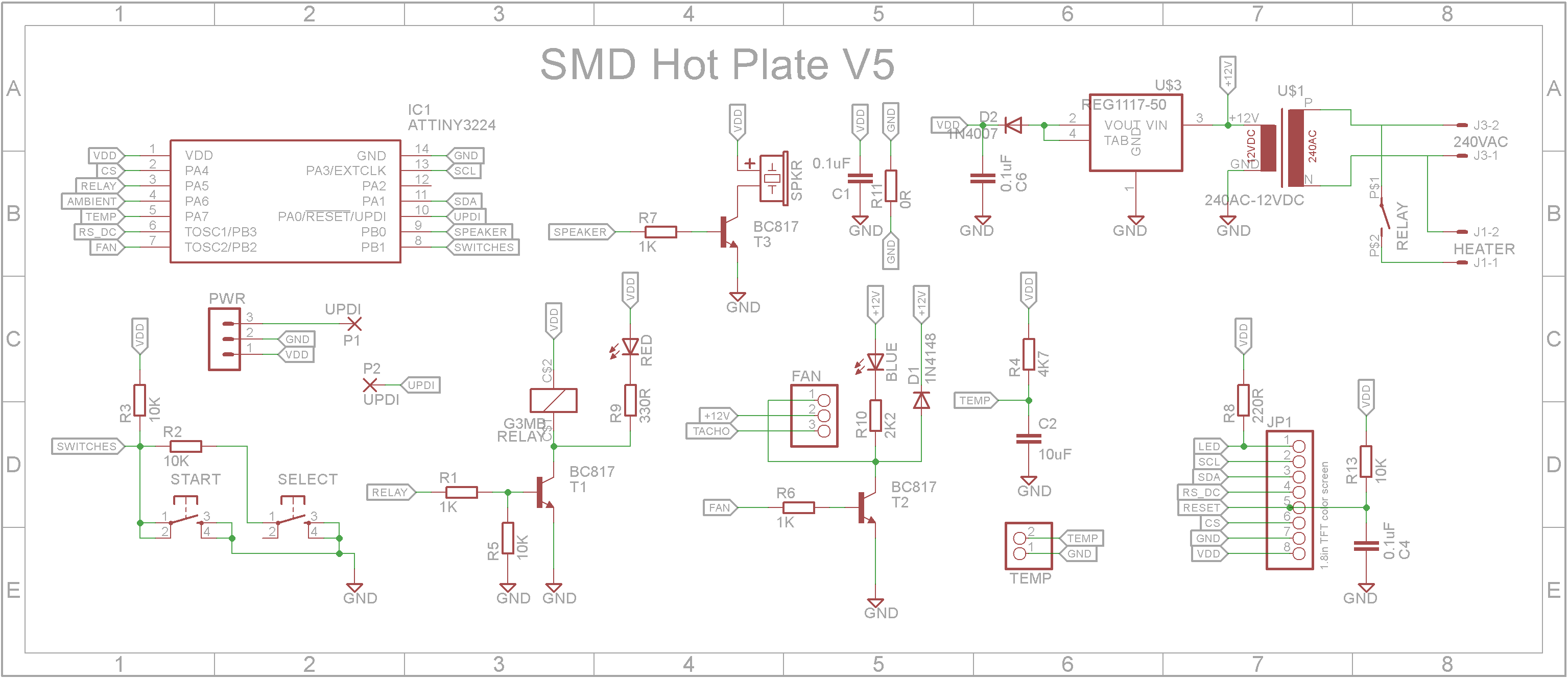
CircuitThe circuit hasn't changed much from the previous version. I upgraded the microprocessor to a ATtiny3224. This has twice the flash memory and more RAM.
The 200mA 2N3904 transistors have been upgraded to 500mA BC817 transistors mainly because the dual fans draw twice the current now. The fans are 12V fans so the 240VAC to 5VDC power module was replaced with a 240AC to 12VDC power module to power the fans and a 5V regulator was added to power the microprocessor, solid-state relay and 1.8in TFT screen.
Also I removed the ambient temperature sensor and set the cool down temperature in software to 45 deg C.
The unit is controlled by two buttons:
SELECT: When in STOPPED mode, it will select the heat curve to use. In PAUSED mode, it will abandon the current heat curve.
START: When in RUNNING mode, it will pause the at the current temperature in the heat curve and maintain that temperature until the START button is pressed again. In STOPPED mode, it will start the displayed heat curve from the beginning.
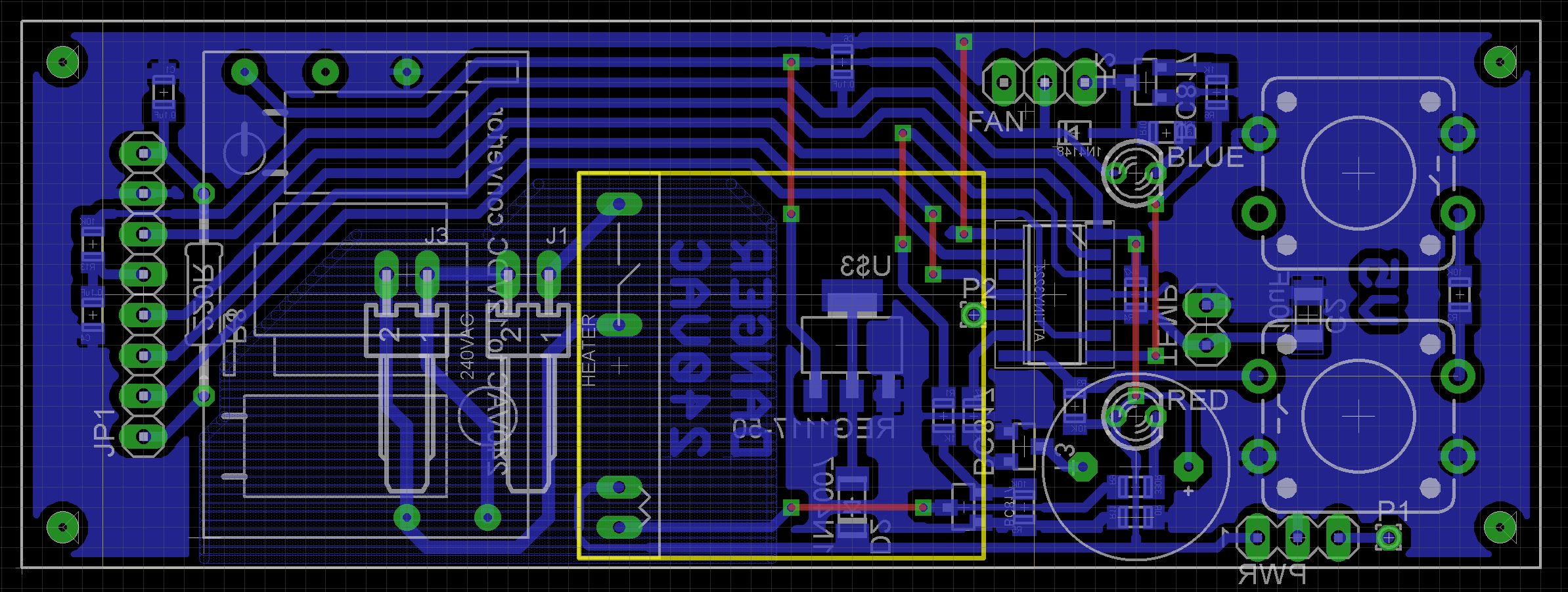
AssemblyI have included the Eagle files in case you want to get the board commercially made or do as I did and make it yourself. I used the Toner method.
Start by adding the SMD components
Add any links if your board is single sided
Add two 3-pin straight headers to the copper-side of the board for the fan and UPDI programmer. If you use a header on a single sided board, here is the method I use to add them. Place header on PCB with longer pin side down, solder pins, push black plastic down towards the PCB.
Add a 2-pin straight header to the copper-side of the board for the thermistor.
Add the 220 ohm through-hole resistor.
Add a wire from the connection near the UPDI pin on the microprocessor to the connection next to the UPDI pin on the UPDI programmer pin header.
Add the two right-angle KF2510 2.54mm 2-pin male connectors for the power and heater connections
Add the two 12x12mm tactile switches. 3D print "SHP - Button Extender.stl". Add the extenders to the buttons and push on the button tops.
Add the female 2.54mm Dupont header for the display
Add the solid state relay. It lies flat on the PCB.
3D print "SHP - TFT Spacers.stl" and super glue them to the board.
Add the 240VAC to 12VDC 450mA module to the copper side of the board. Add a small amount of packing under the module so it doesn't short out on anything.
3D print "400 - Cage.stl". This will fit over the power supply module to protect your fingers accidentally touching it while the unit in powered up.
Next place the LEDs in their holes but don't solder them yet. Make sure they are correctly orientated first.
Screw on the PCB to the front using 4 x M2 6mm screws.
Push the LEDs into their corresponding countersunk holes and solder them to the board. Cut off any access wire.
Next add the active buzzer. (A passive buzzer won't work).
Add the safety cover to protect yourself from any accidental electric shocks.
Now would be a good time to program the microprocessor - see next section.
Add the fan assembly to the case if you haven't already done so.
The two fans I used were 3 wire fans. The white tachometer wire is not used. Do not connected them together. Just leave them insulated from each other. The power wires are connected in parallel.
Finally wire up the fan and mains socket.
When joining the clam shells, put the hot plate through the hole in the top, screw the shells together using 4 x M3 6mm screws.
The software makes use of the attached thermistor library by Miguel Angel Califa Urquiza.
The software can hold any number of heat curves. A plot is a series of six pairs of temperature and time values. The time is the number of seconds from the start to when that temperature should be reached. A temperature of zero will be considered the end of the heat curve and any other slots ignored.
Originally I had the tables in flash memory but because flash memory is very tight, I moved them to the static RAM (Data space).
If you add to the number of plots, don't forget to increase the NUMBER_OF_PLOTS definition and also append a reference to your new plot in the plots array.
#define TABLES_IN_DATA_SPACE
typedef struct {
    int temp;     //Temperature to reach
    int period;   //Seconds to reach temperature
} TARGET;

#define NUMBER_OF_PERIODS 6
#ifdef TABLES_IN_DATA_SPACE
const TARGET plot1[NUMBER_OF_PERIODS] = {{150,90},{150,180},{240,240},{240,260},{0,420},{0,0}};
const TARGET plot2[NUMBER_OF_PERIODS] = {{150,50},{180,140},{240,175},{240,185},{120,250},{0,350}};
const TARGET plot3[NUMBER_OF_PERIODS] = {{150,60},{200,120},{250,160},{250,190},{0,260},{0,0}};
#else
const TARGET plot1[NUMBER_OF_PERIODS] PROGMEM = {{150,90},{150,180},{240,240},{240,260},{0,420},{0,0}};
const TARGET plot2[NUMBER_OF_PERIODS] PROGMEM = {{150,50},{180,140},{240,175},{240,185},{120,250},{0,350}};
const TARGET plot3[NUMBER_OF_PERIODS] PROGMEM = {{150,60},{200,120},{250,160},{250,190},{0,260},{0,0}};
#endif

#define NUMBER_OF_PLOTS 3
const TARGET* plots[NUMBER_OF_PLOTS] = {plot1, plot2, plot3};
The other variable you may need to adjust is the MAX_PID_VALUE. If your hot plate can't reach the desired temperature, you can increase this value. It has a range of 0 to 255 and controls the maximum PWM ON period.
#define MAX_PID_VALUE 180 //Max PID value. You can change this.Unlike the earlier ATtiny series such as the ATtiny85, the ATtiny1614 uses the RESET pin to program the CPU. To program it you need a UPDI programmer. I made one using a Arduino Nano. You can find complete build instructions at Create Your Own UPDI Programmer. It also contains the instructions for adding the megaTinyCore boards to your IDE.
Once the board has been installed in the IDE, select it from the Tools menu.
Select the ATtiny3224 board in your IDE
Select Board, chip, clock speed, COM port the Arduino Nano is connected and the programmer
The Programmer needs to be set to jtag2updi (megaTinyCore).
Open the sketch and upload it to the ATtiny3224.
ConclusionsGuaranteed that this will get a lot of use based on the amount of use my smaller 200W variant got. The cooling system works quite well so all in all a very useful project.


Comments
Please log in or sign up to comment.