


Hardware components | ||||||
| × | 1 | ||||
| × | 3 | ||||
| × | 6 | ||||
 |
| × | 6 | |||
 |
| × | 3 | |||
 |
| × | 1 | |||
| × | 1 | ||||
Hand tools and fabrication machines | ||||||
 |
| |||||
 |
| |||||
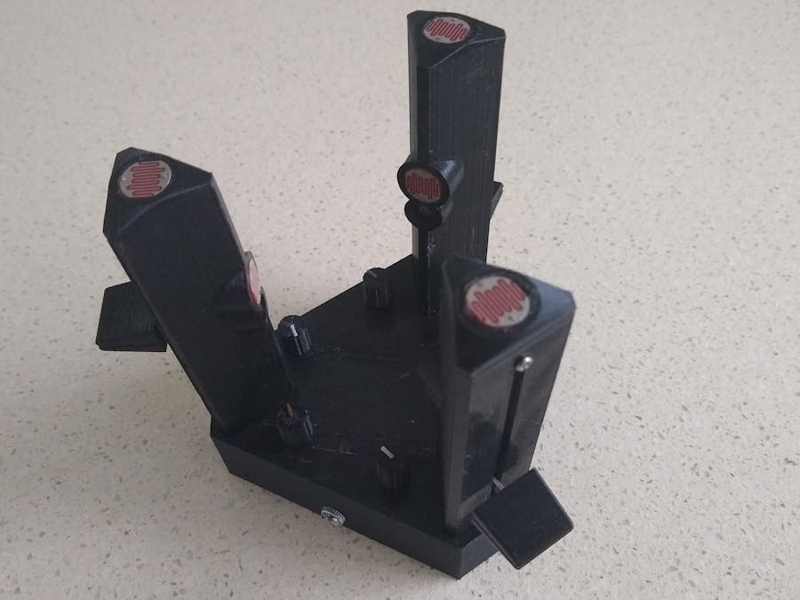
Recently gamezero provided an Instructable for his Trident, 3-Voice Light Theremin. Unfortunately I couldn't source the Light Dependent Resistors (LDR) that he used. The best I could find was either too small or too large. So instead I got some 12mm LDRs and decided to redesign the towers to use these instead.
3D design changesOne of the issues I faced when using gamezero's design was I couldn't get the slider potentiometer into the towers. So in my redesign, I separated the back from the tower and glued it back on once the components were in place and wired up. The redesign also incorporated the top LDR holder into the holder that holds the side LDR and LED making it a single piece.
It was always my intention to mount all the components in the base on a single PCB. The potentiometers around the base are PCB mounted variants and are no longer screwed onto the base. So the base was redesigned with smaller potentiometer holes and PCB mounting posts.
I didn't bother designing a suitable base plate as all components are firmed fixed in place.
3D printingAll files required for 3D printed are attached. I also 3D printed all the knobs as well.
"Trident - Base.stl" - 0.2mm layer height, no supports, 1 off
"Trident - Tower Lower.stl" - 0.2mm layer height, no supports, 3 off
"Trident - Tower Upper.stl" - 0.2mm layer height, all supports, 3 off
"Trident - Tower Slider Knob.stl" - 0.2mm layer height, no supports, 3 off
"Trident - Base Rotary Knob.stl" - 0.2mm layer height, no supports, 6 off, change to contrasting filament at the start of layer 56.
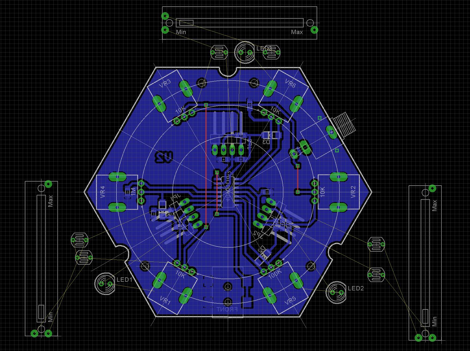
Printed Circuit BoardAll the electronics, with exception of the tower components and headphone socket are mounted on the PCB. The towers are connected to the PCB via 4 way Dupont connectors. The PCB is fixed to the base using 4 x M2 6mm screws.
The Eagle files have been included should you wish to get the board commercially made or you can make it yourself. I used the Toner method to make mine.
Start by adding the SMD components.
Next add the links if you are using a single sided PCB
Add the three right angle pin headers to the copper side of the board. I used a dab of paint to match the color of the wires coming in from the towers. Note that the bottom-right pin header (as shown in the image below) has the red and yellow wire positions swapped. This was done to simplify PCB track routing.
Add the 6 rotary pots. Make sure you get the 1M and 100K pots in their correct position.
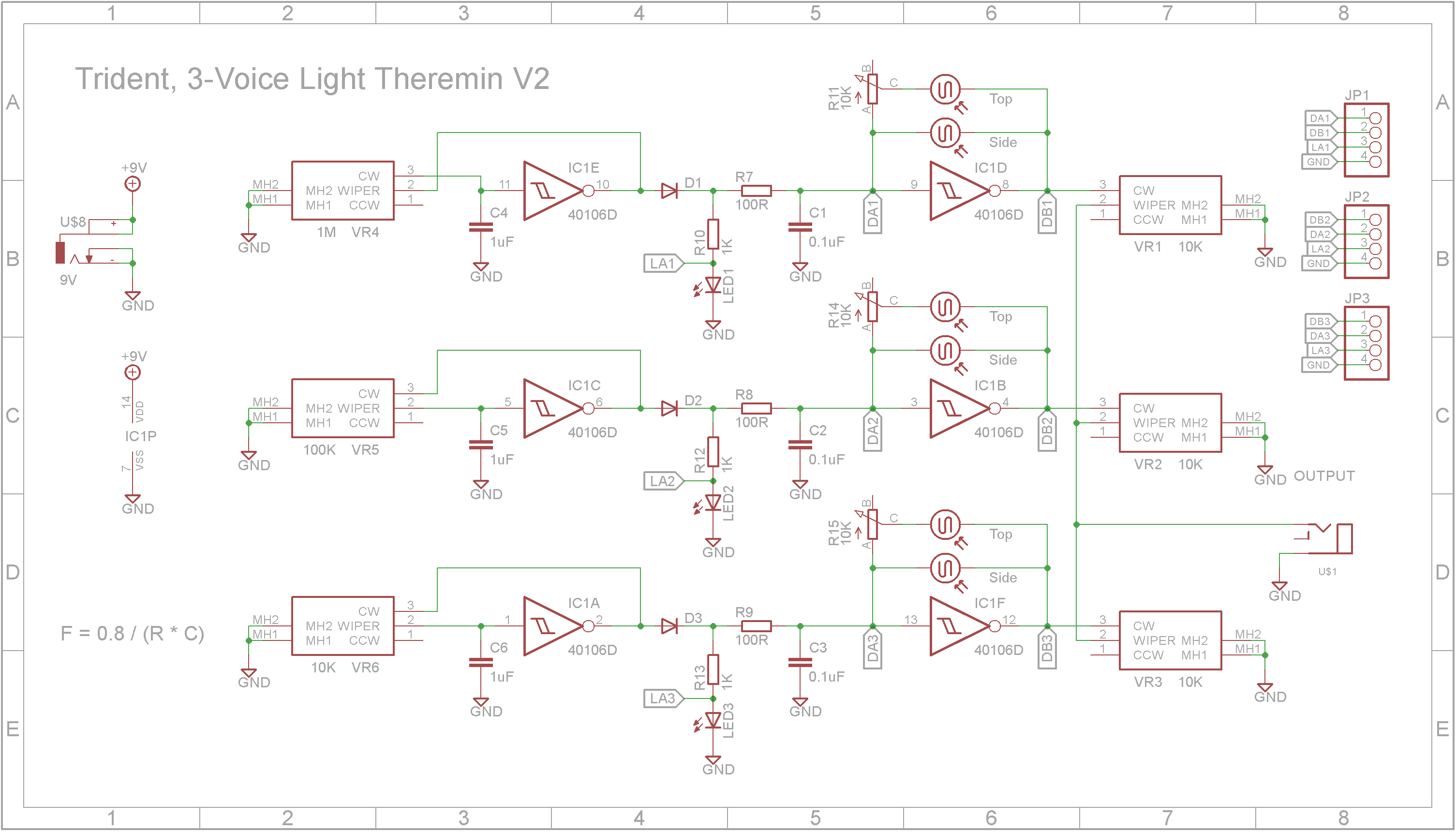
Each tower consists of two LDR's, a LED and a slider potentiometer. Wire them up according to the diagram below. Take care with the orientation of the LED. The green wire goes to the cathode and the purple wire goes to the anode. Once wired, use super glue to glue the two parts of the tower together.
Note: The "Trident - Tower Upper.stl" is different than the one shown in the diagram below. The new one was designed to be fixed to the base using a screw. (not implemented in this version).
I used double sided tape to fix the towers to the base. You could also use super glue. Cut the wires from each tower to length and add 4 way female Dupont headers to the ends. You can purchase female-to-female 40 way 10cm cables from sites like eBay or AliExpress if you don't want to add your own Dupont connectors.
My original plan was to mount the headphone jack onto the PCB. However this would of stopped the board from being inserted into the case. So instead separate wires were added and the ends soldered directly onto the PCB.
The wires from each tower need to be connected first before the PCB is lowered into place. Make sure the wires for the tower stay in the channels provided on the PCB. Once the PCB is seated, screw it in place using four M2 6mm screws.
Screw the headphone jack into its hole.
Connect the unit to an amplifier via the audio jack and feed 9V to the DC power jack from a battery or power brick.
Thanks gamezero for a great project. It took a while to overcome some of the setbacks like not being able to source the components you used but it all came right in the end. 😃


Comments
Please log in or sign up to comment.