Most of the projects that I build have a custom printed circuit board. With a preference to making my own PCBs rather than using proto-boards, the minimum track width is usually limited by the method used to make the board. With the Toner method, minimum track width is about 0.016in. To create smaller tracks than this, photographic methods are better suited.
There are a number of tutorials on how to create a board using the photoresist method so I won't cover it here. See DIY PCB Using Liquid Photoresist for one such method.
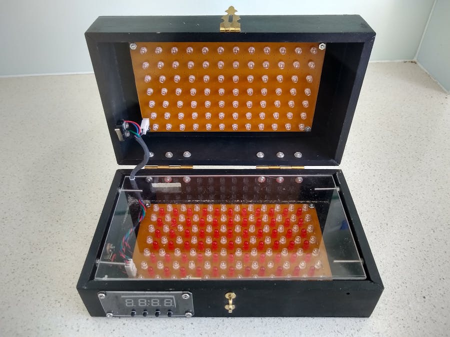
This project is about creating a UV exposure box to cure the photoresist. I based my design on the LED UV exposure box by Electrobob. The box was built from 40mm x 9mm dressed pine with the top and bottom covered with 3mm MDF. The hinges and clasp was purchased from a local hardware store. The dimensions of the final box is 233mm x 140mm x 86mm.
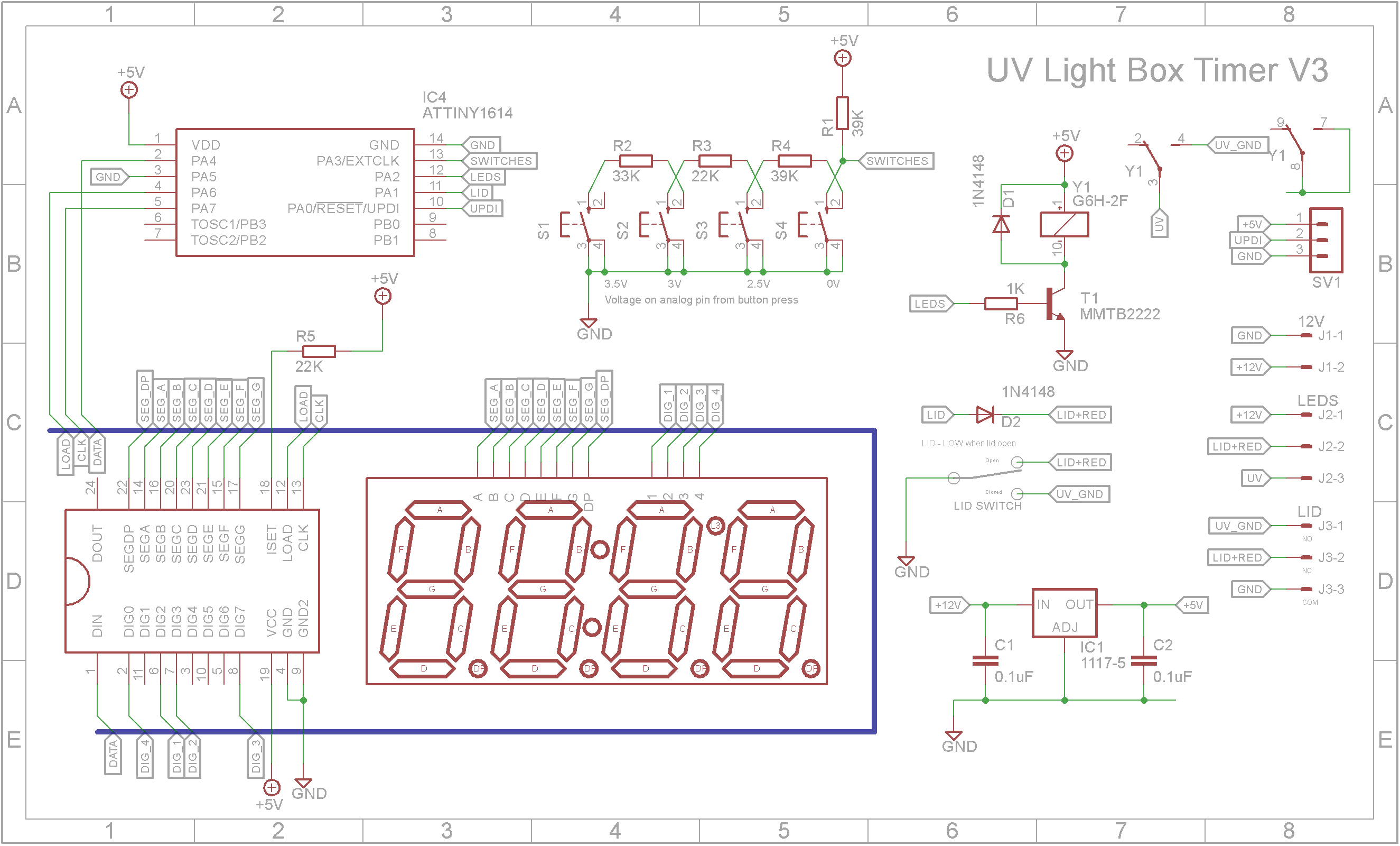
The timer is built around the ATtiny1614 microprocessor. The 4-Digit 7-Segment display is driven by a MAX7219 LED driver. The four switches are connected to a voltage divider which is read by the microprocessor as a analog value. The UV LED lights are switched on via a relay.
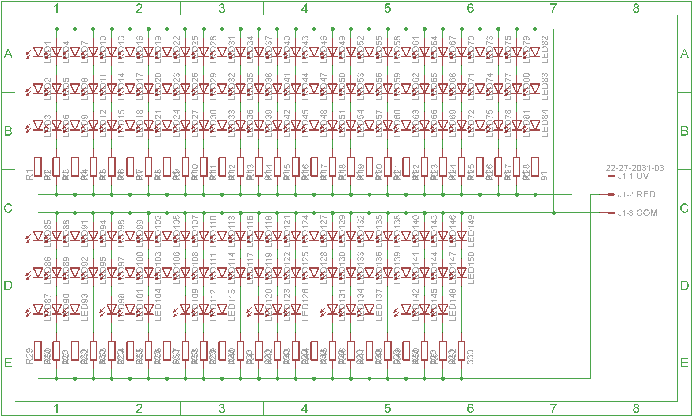
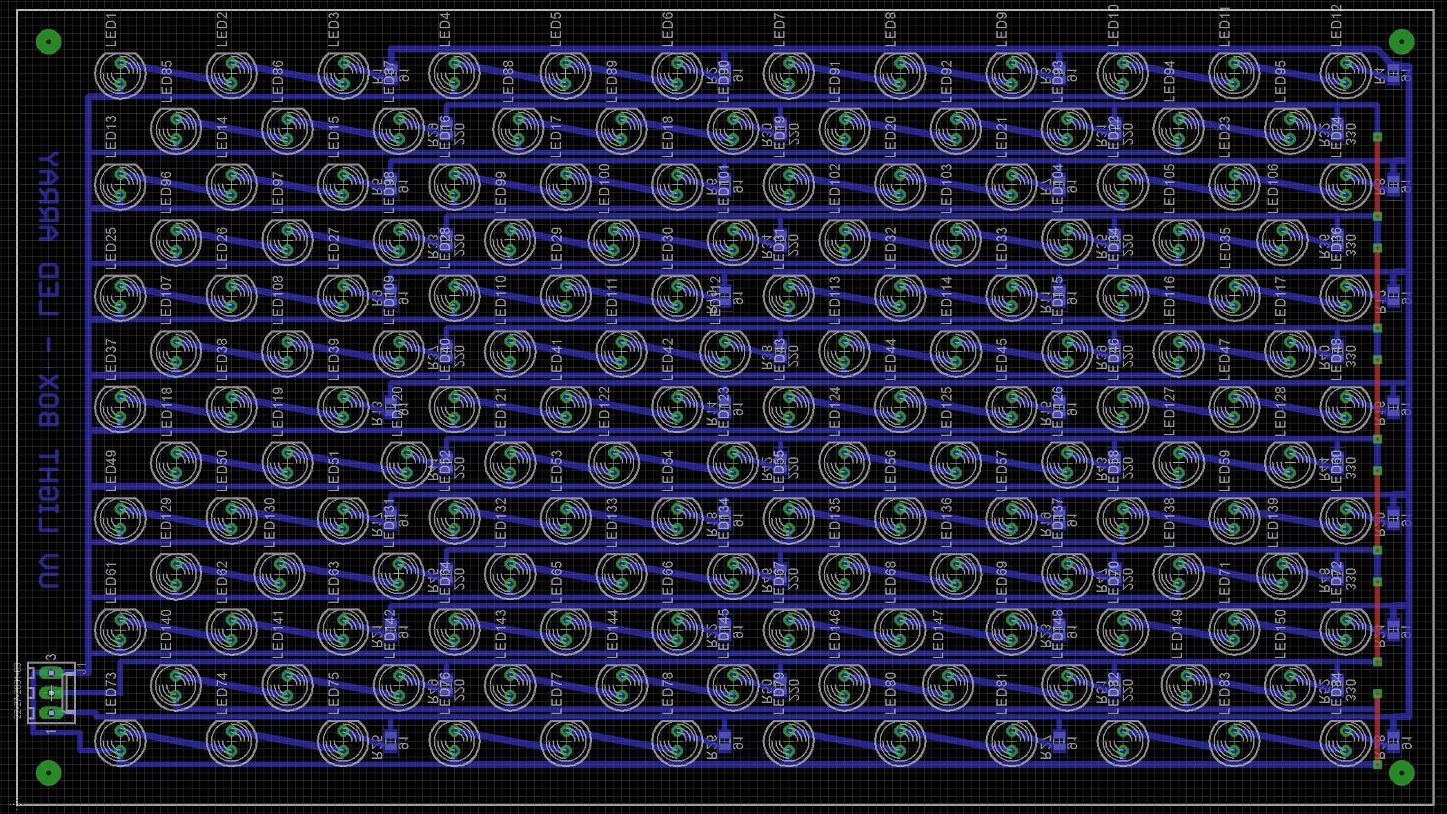
The LED boards contain 84 Ultraviolet LEDs each. The lower board also contains 66 Red LEDs. There is a micro-switch that closes when the lid is closed. The unit will automatically pause and switch off the UV LEDs when you open the lid to protect your eyesight. The red LEDs switch on when the lid is open so that when creating double-sided boards, the red light will shine through the alignment holes.
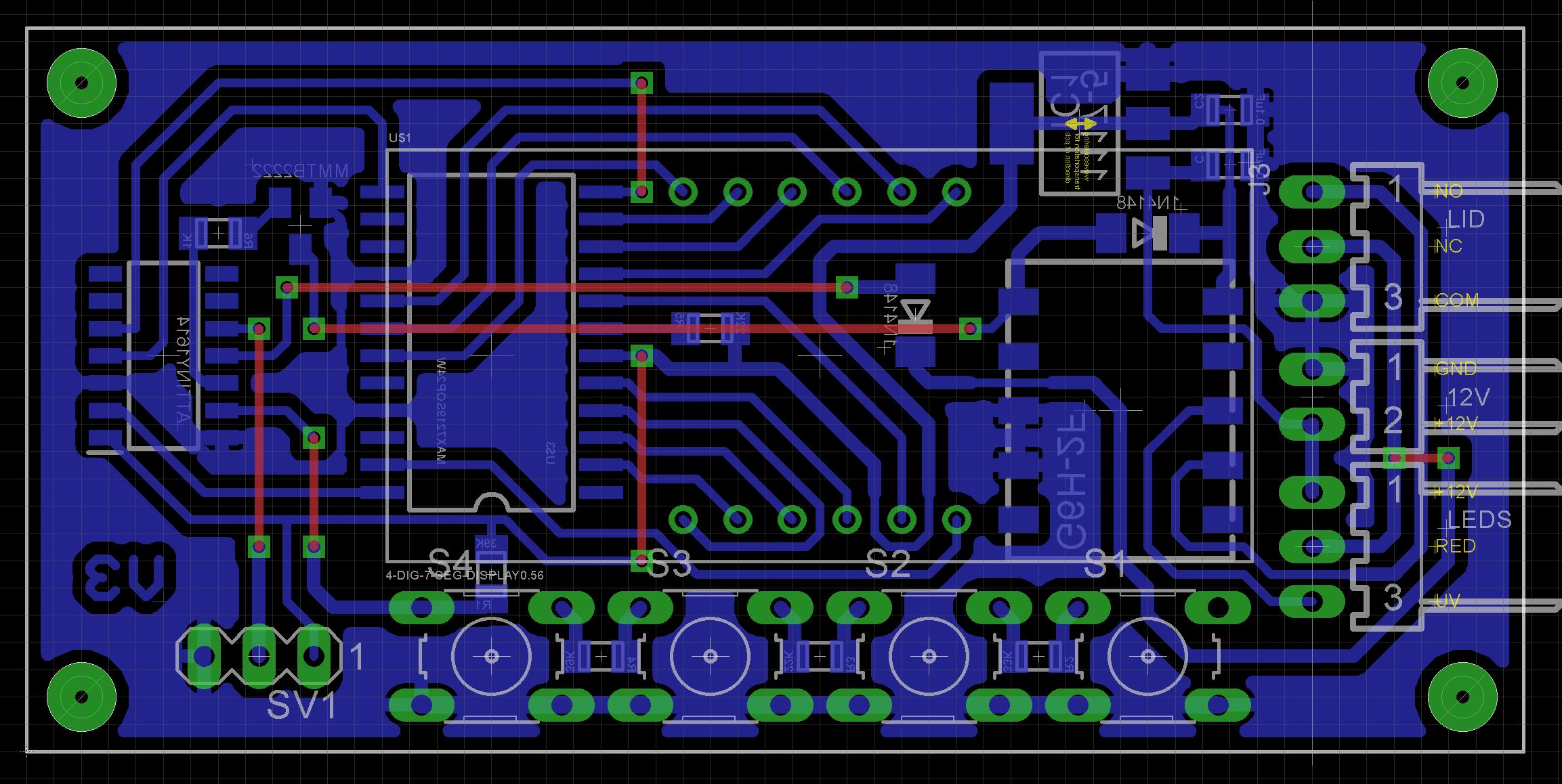
With the exception of the switches and display, all components are surface mount components.
The Eagle files have been included in case you want to get the board commercially made or do as I did and make it yourself. I used the Toner method.
Start by adding the SMD components. I find it easier to use solder paste rather than use solder from a reel when soldering SMD components.
Add the links if your board is single sided.
Next add the headers. If your board has through hole plating, you can solder the wires directly to the board rather than use connectors. On the UPDI header, dab a bit of red paint on the +VE pin since pin headers aren't polarized. This will allow you to know to which end the red wire goes to.
Add the display and buttons.
The ATtiny1614 is part of the new breed of ATtiny microprocessors. Unlike the earlier series such as the ATtiny85, the new breed use the RESET pin to program the CPU. To program it you need a UPDI programmer. I made one using a Arduino Nano. You can find complete build instructions at Create Your Own UPDI Programmer. It also contains the instructions for adding the megaTinyCore boards to your IDE.
Once the board has been installed in the IDE, select it from the Tools menu.
Select Board, chip, clock speed and the COM port that the Arduino Nano is connected to.
The Programmer needs to be set to jtag2updi (megaTinyCore).
Open the sketch and upload it to the ATtiny1614.
Using the UV exposure boxFrom the left, the four switches are MENU, DECREASE, INCREASE, START/STOP
On power on, the last time period that was used will be displayed. If you wish to change it, press the MENU button and the minutes value will flash. Use the INCREASE or DECREASE buttons to set the minutes value. Pressing the MENU button again will allow you set the seconds. Once you have set the seconds, press the MENU button to set the display brightness. Pressing the MENU button for the fourth time will take you back to STOP mode.
After you place the film and PCB on the plate, close the box and press the START/STOP button. The UV lights will come on and the timer will start to count down to zero. Pressing the START/STOP button or opening the lid while the unit is on will turn off the UV lights and pause the timer. Once the timer reaches zero, it will automatically switch off the UV lights.






Comments
Please log in or sign up to comment.