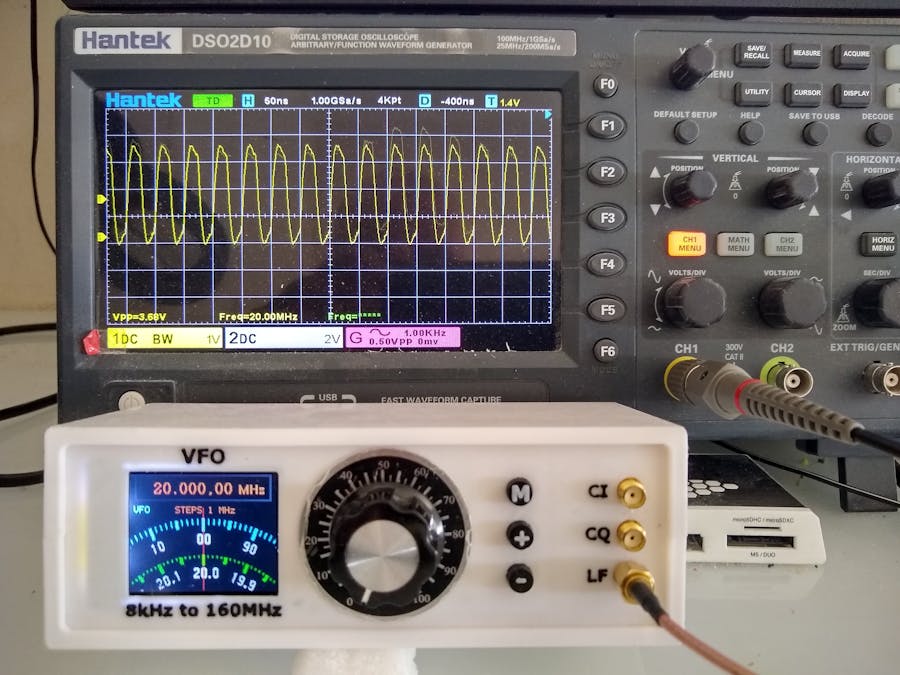
This is my remake of Mirko Pavleski's Universal VFO 10 KHz-160 MHz with Retro Analog Scale project.
The Si5351 Clock Generator has three independent outputs. Each one can have a different frequency. Part of this redesign is to make the extra two outputs available for a future software upgrade. Also I wanted to redesign the case to make it more suitable for my benchtop by reducing the overall size.
Demonstration3D printingThe case is a clam-shell design.
"VFO - Back.stl" - 0.2mm layer height, no supports, rotate 90deg about the Y axis
"VFO - Bottom.stl" - 0.2mm layer height, no supports
"VFO - Top.stl" - 0.2mm layer height, no supports, rotate 180deg about the Y axis
"VFO - Front.stl" - 0.2mm layer height, no supports, rotate -90deg about the Y axis
"VFO - Text.stl" - 0.2mm layer height, no supports, rotate 90deg about the Y axis, change filament to a contrasting color at the start of layer 4
"VFO - Buttons.stl" - 0.2mm layer height, no supports, change filament to a contrasting color at the start of layer 36
"VFO - EspSpacer.stl" - 0.1mm layer height, no supports
"VFO - TftSpacer.stl" - 0.1mm layer height, no supports
Using double sided tape or glue, fix "VFO - Text.stl" to "VFO - Front.stl".
The round dial plate and knob used for the rotary encoder on the front panel can be purchased from sites like eBay or AliExpress. Search for "A03 dial knob".
The lugs that hold the shells together are a bit fragile. I glued on washers before I drilled the holes with a 2.5mm drill and created a thread with a 3mm tap. Drill out the holes that the screws go through with a 3mm drill.
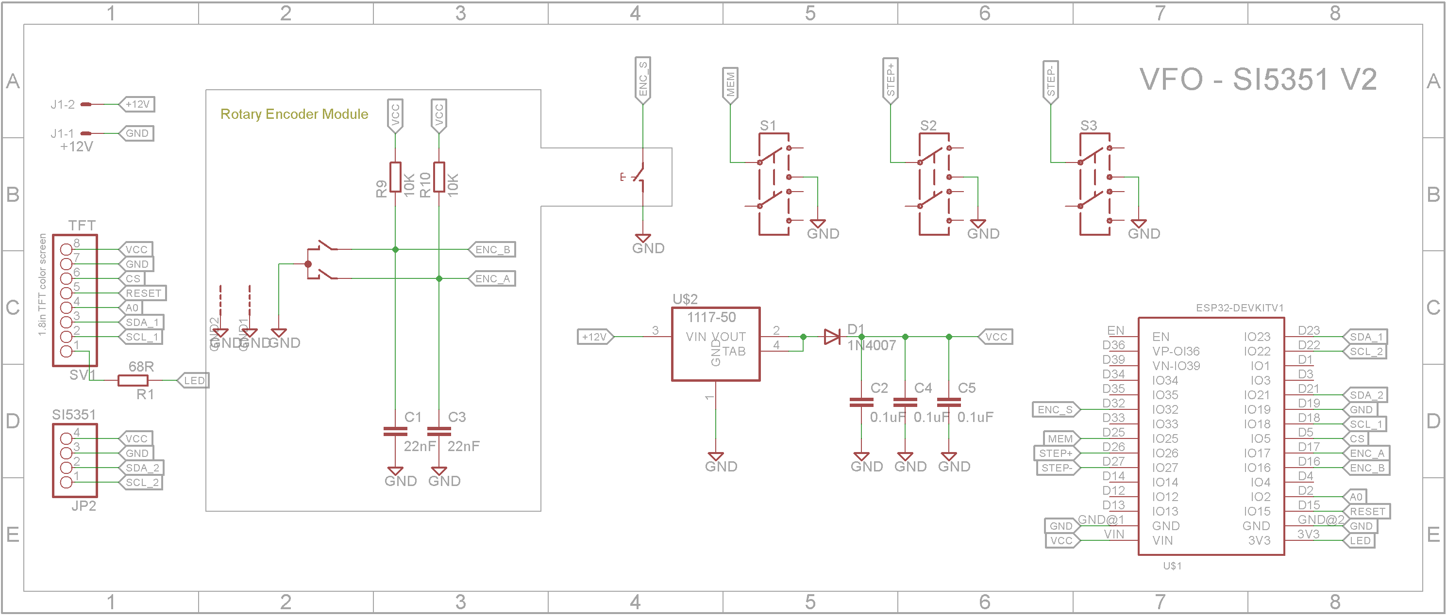
The PCB is designed to be fixed to the front panel and eliminates most of the wiring. The Eagle files have been included should you wish to have the board commercially made or you can do as I did and make it yourself. I used the Toner method.
Start by adding the SMD components. I find it easier to use solder paste rather than use solder from a reel when soldering SMD components.
Add the links if your board is single-sided.
Add the four pin header for the connection to the Si5351 module to the copper side of the board.
Next add long pin female headers to the pins on the ESP32 Dev Kit. Use the 3D printed supports to position the module on the copper side of the board before soldering the pins in place. I also super glued the supports to the female headers to provide extra strength to the connectors when removing or inserting the ESP32 Dev Kit module.
Add the 2 pin polarized header for the power to the copper side of the board.
Assembly - Step 3Add a female pin header for the 1.8in TFT display module. Position the display module on the component side of the board and super glue the 3D printed supports to the PCB. Solder in the female pin header for the TFT display once the glue has dried.
Add the push button momentary 8x8 switches to the PCB. The picture shows yellow button tops but I ended up replacing these with the 3D printed ones.
Add the 25mm D-Shaft rotary encoder.
Plug in the 1.8in TFT display.
Using two 4mm M2.5 screws, screw in the Si5351 oscillator board to the front panel.
Screw the main board to the front panel using four 6mm M3 screws.
Add a cable with 4 pin Dupont female headers at both ends. You can either make this yourself or buy them from sites like DIYables. (https://www.hackster.io/diyables/products/jumper-wires).
Assembly - Step 6Add the DC power socket to the back panel and wire up to the PCB.
Before closing the clam-shell case, plug in the USB cable to the ESP32 Dev Kit and upload the software via the Arduino IDE.
The Software was written by T.Uebo / JF3HZB. It appears to be designed to output a in-phase carrier frequency (CI) on channel 0, a 90 degree out of phase (quadrature) carrier frequency (CQ) on channel 1 and a modulating low frequency on channel 2. However it also appears that only channel 2 has been implemented at this stage. The software sets the output frequency range to 100kHz to 16OMHz even though the Si5351 module can go down as low as 8kHz.
The only change that I made to the software from the version used by Mirko was to flip the output to the display since I had unknowingly put the TFT the opposite way round when designing the PCB.
ConclusionOverall the final appearance looks nice on the benchtop. The output from the Si5351 module is more a square wave than a sine wave which is unfortunate. It sort of limits its usefulness to providing clocks for digital circuits.
All-in-all, it was a fun build, it looks professional so thanks Mirko for another great project.


Comments
Please log in or sign up to comment.