


Hardware components | ||||||
| × | 1 | ||||
| × | 1 | ||||
| × | 4 | ||||
| × | 4 | ||||
| × | 1 | ||||
| × | 1 | ||||
| × | 2 | ||||
| × | 1 | ||||
 |
| × | 2 | |||
Software apps and online services | ||||||
| ||||||
Hand tools and fabrication machines | ||||||
 |
| |||||
 |
| |||||
| ||||||
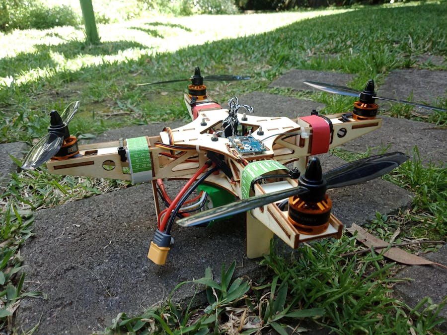
I wanted to prototype a quadrotor frame out of laser cut plywood. This was also my first attempt at making a drone from scratch (for later addition of a action camera for in-flight footage/basic aerial photography). A full design process was followed - conceptual design, thrust-weight ratio calculations, weight/cost budget, CAD etc
CAD AssemblyDesigned the parts for the laser-cut DXF files using AutoDesk Fusion360. My chosen material was 3mm plywood. The various parts slot together as inspired by ideas at http://www.shendrones.com/booboo. The parts are described as follows:
- Chassis Upper x 1
- Chassis Lower x 1
- Motor Pad x 4
- Legs x 4
- Rotor Arm x 8
The CAD files were then converted into DXF for use on the university laser cutting machine
The assembly of the drone required some fasteners (only 4 x standoffs and shock mount hardware) with the usual flight controller footprint. The rest was glued together using wood glue.
A major part of a successful (and flyable) quadrotor is the thrust-weight ratio which essentially is a measure of how capable the drone is to hover and remain manouvreable. For an aerial photography platform, a thrust-weight ratio of 2:1 is sufficient (see https://www.dronetrest.com/t/how-to-choose-the-right-motor-for-your-multicopter-drone/568 for more details). Explanations of my calculations are below:
The weight of the entire drone (battery, assembled frame, motor + props) was found to be 0.531 kg.
From the spec sheet for my motor, the BE1806 2300kV motors provide 0.521kg of thrust at 100% throttle.
So the total available thrust is 4 x 0.521kg = 2.084kg at 100% throttle
To hover, the minimum available thrust should be 0.531kg, so the usable thrust is then 2.084 / 0.521 = 3.9. This means that the thrust to weight ratio is 3.90 which would result in quite an agile drone.
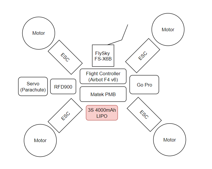
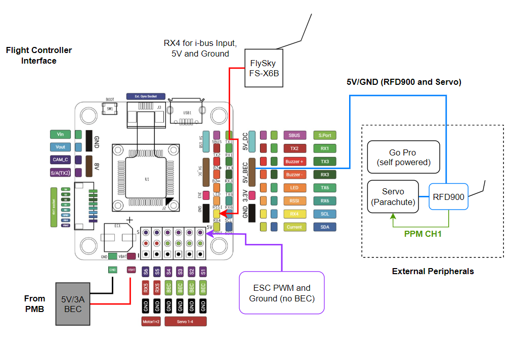
Flight Testing GearThe flight transmitter was a FlySky FS-i6 (https://www.flysky-cn.com/fsi6). Instead of using the provided FS-iA6B receiver, I decided to use the iBus capable FlySky FS-X6B Receiver (https://img.banggood.com/file/products/20160924022953FS-X6B%20Receiver%20User%20Manual.pdf) to future-proof the design.
Flight time was around 12 minutes using a Turnigy 4000 mAh 3S LiPO
Due to the fragile nature of the quadrotor frame, I also tested out a failsafe system that could be used to deply a small parachute, using onboard Teensy/RFD900 setup - as another feature for this drone (Work in progress still...)
The Flight Control software I decided to use was Betaflight. This allowed me to set up the PID tuning parameters, iBUS settings and ESC calibration/settings. Majority of the basic set up for the gyro orientation and IMU placement were followed as found on https://blog.dronetrest.com/omnibus-f4-v6-flight-controller-guide/
Motor/ESC Setup
Motor configuration was the conventional Betaflight method for an X frame quadrotor. ESC calibration and direction changes were done through Blheli Configuration (https://chrome.google.com/webstore/detail/blheli-configurator/mejfjggmbnocnfibbibmoogocnjbcjnk?hl=en)
- Motors 1 and 2 were CW (as seen from above)
- Motors 2 and 3 were CCW (as seen from above)
Flight Modes
The main flight mode that would be used is 'Stabilize' mode. I also set up one Switch as an 'Arming Switch'


Comments
Please log in or sign up to comment.