


Hardware components | ||||||
 |
| × | 1 | |||
 |
| × | 1 | |||
| × | 1 | ||||
| × | 1 | ||||
| × | 1 | ||||
Software apps and online services | ||||||
| ||||||
| ||||||
 |
| |||||
The importance of ICT (Information and Communication Technology) is becoming particularly important with the increasing usage of the Internet in all walks of life. People and objects are integrated via the Internet. The Covid-19 pandemic, despite all its negativity, has accelerated this integration.
The name of the project IoT observatio and its abbreviation IoTo consists of the abbreviation IoT for Internet of Things and character 'o' for the Latin word observatio, whose English equivalent is observation. Hereinafter, the abbreviation IoTo will be used.
The goal of IoTo project is to get idea of an IoT infrastructure. I want you, by the end of this, to have a step-by-step guide to connecting devices to your Raspberry Pi, and to Google’s Cloud Platform. That is just a start.
Below are prerequisites if you want to do similar project by yourself:
1. Workstation
- I have used a Linux laptop and several mobile devices
2. Raspberry Pi 4 with an OS installed
- I have used Raspberry Pi OS (previously called Raspbian)
3. Network router with the internet access
- I have used a mobile router Asus 4G-N12 B1
- It’s now a better product after several firmware updates – thanks Asus Technical Support!
4. IoT devices
- I have built and used one ESP32 based device
- I have used several RuuviTag’s; higher number of RuuviTag’s are supported by the design of the IoTo
- You should have at least one IoT device for MQTT Service to make any sense
5. Google Cloud
- Other cloud providers could be used but you need to figure out the details
6. Raspberry Pi Camera module for surveillance feature
- Other camera models should work too
- You can skip this if you are not interested in the surveillance feature
Please check also the Things page.
2. IoTo architectureThe IoTo architecture consists of its own IoT platform and the Google Cloud Platform. The own platform was also physically tested in different places, so it can be called at least playfully as a cloud, My Cloud Platform. The figure (Figure 1) shows the IoTo architecture:
At the top level, IoTo access interfaces are described. Both platforms can be accessed via the Internet from both mobile and workstation devices using the HTTPS protocol.
At the core of My Cloud Platform is the Raspberry Pi, know also as abbreviation rpi, which offers both external and internal services. External services are provided by WWW Service and MQTT Bridge. The WWW Service is implemented by the nginx server, which offers the Raspberry Pi as surveillance camera feature. MQTT Bridge transmits IoT sensor data from the local MQTT Service to the Google Cloud Platform. The function of internal services is to provide the necessary interfaces to external services.
The ESP32 IoT Device communicates with the MQTT Service slightly differently from the figure. The ESP32 IoT Device takes a WiFi connection to the router, after which the sensor data is transmitted via the MQTT protocol to the Mosquitto, or MQTT Service service in the picture.
RuuviTag IoT Devices collect information about their environment which is collected and transmitted by the BLE Service using the MQTT protocol to the Mosquitto, or MQTT Service in the picture.
The Firewall NAT Router concept takes care of the necessary network infrastructure. The network infrastructure is based on the network features of the Asus 4G router, ISP or Internet Service Provider and the Raspberry Pi Linux operating system.
The following sections of the report provides a more detailed overview of the IoT project as a whole and its various aspects.
3. Building IoTo infrastructureThe Raspberry Pi is a versatile device. The Raspberry Pi 4 model B with 4GB of memory used is powerful enough to act as both a gateway to the IoT infrastructure and a Raspberry surveillance camera (Figure 2):
Building up IoTo infrastructure consists of five areas:
1. Raspberry Pi as IoT infrastructure gateway
2. Raspberry Pi as surveillance camera
3. IoT measuring device
4. BLE Service
5 Google Cloud Service
3.1. Raspberry Pi as IoT infrastructure gatewayThe Raspberry Pi IoT infrastructure gateway can be divided into two parts:
1. WWW Service
2. MQTT Service
3.1.1. WWW ServiceThe surveillance camera used with the browser is based on the use of HTTP and HTTPS protocols:
- A secure intranet uses an http connection
- The external network uses a secure https connection, which is terminated by the intranet web server.
WWW Service is provided through an application installed on the nginx web server and the infrastructure is built on it. A more detailed description of the service is in section 3.2. Raspberry Pi as surveillance camera.
3.1.2. MQTT ServiceMQTT Service can be divided into three parts:
1. Sensor data collection
2. Transmission of sensor data
3. Setting up Apache Mosquitto MQTT Broker
3.1.2.1. Sensor data collectionIn accordance with the MQTT protocol, the various sensors publish data to the Mosquitto Broker's own topic on the rpi. The information obtained can be used locally for your own use. Below is a picture of one use case, called the use of sensor data in MQTT Explorer (Figure 3):
Looking good. Please observe sections 3.3. IoT measuring device and 3.4. BLE Service on how the data can be collected.
3.1.2.2. Transmission of sensor dataIn addition to your own use, the information obtained from the sensors can also be passed on to other use cases. Section 3.5. Transmission of sensor data to the cloud describes the transmission of sensor data in more detail.
3.1.2.3. Setting up Apache Mosquitto MQTT BrokerMQTT Service is implemented using Apache Mosquitto Broker software. Eclipse Mosquitto is an open source message broker that implements the MQTT protocol. Installation and configuration are done with the commands (Figure 4):
joker@jrpi01:~ $ sudo -s
root@jrpi01:/home/joker# cd /tmp
root@jrpi01:/tmp# wget http://repo.mosquitto.org/debian/mosquitto-repo.gpg.key
root@jrpi01:/tmp# apt-key add mosquitto-repo.gpg.key
root@jrpi01:/tmp# cd /etc/apt/sources.list.d/
root@jrpi01:/etc/apt/sources.list.d# wget http://repo.mosquitto.org/debian/mosquitto-buster.list
root@jrpi01:/etc/apt/sources.list.d# cd
root@jrpi01:/home/joker# apt update && apt upgrade && apt autoremove
root@jrpi01:/home/joker# apt install mosquitto mosquitto-clients
root@jrpi01:/home/joker# cd /etc/mosquitto/
root@jrpi01:/etc/mosquitto# cp -a mosquitto.conf mosquitto.conf.ori
root@jrpi01:/etc/mosquitto# vi mosquitto.conf
root@jrpi01:/etc/mosquitto# diff mosquitto.conf mosquitto.conf.ori
14,18d13
<
< # User must exists & login
< allow_anonymous false
< password_file /etc/mosquitto/pwfile
<
root@jrpi01:/etc/mosquitto# mosquitto_passwd -c /etc/mosquitto/pwfile joker
root@jrpi01:/etc/mosquitto# service mosquitto restart
Figure 4: Installation and configuration of Mosquitto Broker
3.2. Raspberry Pi as surveillance cameraThe Raspberry Pi also works great as a surveillance camera. In its simplest form, the camera module is connected to the Raspberry Pi and the package is hung in a suitable place, as shown in figure (Figure 5):
In addition, suitable software is required. There are many options. One excellent option is the RPi Cam Web Interface. RPi Cam Web Interface is a browser-based interface for an application that provides rich features for managing a Raspberry Pi camera (Figure 6):
The figure (Figure 6) shows an example of a ready-made surveillance camera application. The phone's browser uses an encrypted connection using the HTTPS protocol.
3.2.1. Setting up Raspberry Pi cameraOnce you have the necessary equipment, you should start by making sure that the equipment is installed and working. Good instructions can be found in the camera documentation.
3.2.2. Installing needed softwareGit is a distributed version control system. Nginx is a web server. Updating and installing OS-level git and nginx software on the Raspberry Pi (Figure 7):
root@jrpi01:~# apt update && apt -y upgrade && apt -y autoremove
root@jrpi01:~# apt install git nginx
Figure 7: Installing needed software
3.2.3. Installing RPi Cam Web Interface applicationApplication is installed with commands below on the Raspberry Pi (Figure 8):
joker@jrpi01:~ $ cd src
joker@jrpi01:~/src $ git clone https://github.com/silvanmelchior/RPi_Cam_Web_Interface.git
joker@jrpi01:~ $ cd RPi_Cam_Web_Interface
joker@jrpi01:~/src/RPi_Cam_Web_Interface $ ./install.sh
Figure 8: Installing the application
The installation program, install.sh, asks following information (Figure 9):
After successful installation, the application is tested locally from a machine on the subnet with a browser (Figure 10):
What exactly happened above? The application installer installed the necessary utilities, configured them according to the configuration, and launched the necessary programs so that the application itself could be accessed from the LAN by the browser – cool! Next, the use of the application from the public internet will be observed.
3.2.4. Using the application from the internetUsing the application from a public network via the Internet is a basic use case for surveillance camera use. The camera equipment can be installed in location A and monitored from location B or C. A few additional options are required for the use case:
1. Public domain
2. Public IP address
3. Adequate security
3.2.4.1 Public domainUsing the application from the public network via the Internet is a clear use case for surveillance camera use. The camera hardware can be installed in location A and monitored from location B or C. A few Additional Configurations are required for the use case. In terms of straightforward use, the so-called public domain is an essential feature. There are several options, the Dynu service is used here.
Dynu offers a free third level domain name to the registered user. That is, the first part of the three levels is user selectable from the free names. Here, the name my69cloud.mywire.org is used, to which incoming requests can be directed to your own server. Below is a view of the DDNS user interface (Figure 11):
A public IP address is required to access a server application from a public network. The IPv4 address space is limited, so a LTE internet connection might be shared with multiple users. Please ensure from your ISP that the connection is accessible from the internet.
3.2.4.3. Adequate securityAdequate security is a relatively relative concept. A relatively safe way is not to connect the device to any network. The other extremity is to connect the device to networks and hope that no one is interested in the services the device provides.
When the device is connected to the Internet, it is immediately subject to inquiries from the outside world. Poorly secured devices with their services typically have no time to be available until the telecommunications operator begins to threaten to close the subscription.
3.2.4.3.1. Router securityThe router used is essential for security. The first thing to do is change default identities right away. Even before adding a SIM card in case of a mobile router. You should check for updates to your device regularly and install any updates immediately.
3.2.4.3.2. Router configurationAn essential feature is address translation, which covers a terms such as:
• NAT, Network Address Translation
• NAPT, Network Address Port Translation
• PAT, Port / Address Translation
Another essential feature is Port Forwarding, which directs an outbound request to a specific port on a subnet machine. In addition, a static IP address is required for the target machine on the subnet, which can be implemented either by the router or by the target machine. The router feature is used here. Below is a picture of the router's interface, which sets the public IP ports 80 and 443 to control the subnet rpi machine to ports 80 and 443, where the nginx web server is listening (Figure 12):
Tip: port 80 can be disabled and enabled only when needed.
3.2.4.3.3. Server securityYou should regularly check for updates to the server and install any updates immediately. You may want to perform a simple routine rather too often than infrequently (Figure 13):
root@jrpi01:~# apt update && apt -y upgrade && apt -y autoremoveFigure 13: Keep the server up to date
3.2.4.3.4. Server configurationThe nginx web server used must be taught to use an encrypted connection. The connection is encrypted with the HTTPS protocol from the user's web browser all the way to the web server. The server requires an SSL certificate for the HTTPS protocol. Here, a certificate issued by the Let’s Encrypt organization is used. The certbot program asks for removing HTTP access so please be sure to choose the redirect option. The following commands add support for the HTTPS protocol to the server (Figure 14):
root@jrpi01:~# apt install python-certbot-nginx
root@jrpi01:~# certbot --nginx --domain my69cloud.mywire.org
... # clip from the output: start
Please choose whether or not to redirect HTTP traffic to HTTPS, removing HTTP access.
- - - - - - - - - - - - - - - - - - - - - - - - - - - - - - - - - - - - - - -
1: No redirect - Make no further changes to the webserver configuration.
2: Redirect - Make all requests redirect to secure HTTPS access. Choose this for
new sites, or if you're confident your site works on HTTPS. You can undo this
change by editing your web server's configuration.
- - - - - - - - - - - - - - - - - - - - - - - - - - - - - - - - - - - - - - -
Select the appropriate number [1-2] then [enter] (press 'c' to cancel): 2
Redirecting all traffic on port 80 to ssl in /etc/nginx/sites-enabled/my69cloud.mywire.org
... # clip from the output: end
Figure 14: Server traffic encryption settings and implementation
Once you've completed the steps above, the app should respond to any browser connected to the Internet from the URL you use - please don't use mine!
3.3. IoT measuring deviceThe IoT measuring device is a prototype that was made to test certain features required of an IoT device. It measures temperature and humidity, and sends the data to the IoTo infrastructure. The figure (Figure 15) shows the device performing its mission:
The IoT measuring device consist of following components:
1. ESP32 development board
2. DHT11 sensor
3. Circuits
4. Firmware
5. Battery
6. Casing
3.3.1. ESP32 development boardESP32-DevKitC V4 is a small-sized ESP32-based development board produced by Espressif.
3.3.2. DHT11 sensorDHT11 is a basic temperature and humidity sensor which provides a pre-calibrated digital output. Depending on your needs it might be better to use other sensor at least if below zero Celsius degree is needed.
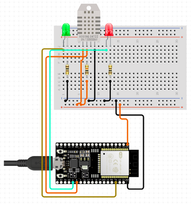
3.3.3. CircuitsA temperature sensor was connected to the development board. In addition, a green and red LEDs were connected for the status information (Figure 16):
Please see the Schematics page for detailed circuits in the circuito.io format.
3.3.4. FirmwareIn order to function, the measuring device needs software, which implements the functions defined for it in a suitable form for the ESP32 hardware. This entity is called firmware. Functions can be created using the Arduino IDE programming environment (Figure 17):
Minimizing the power consumption of the device is an essential factor when using the device wirelessly. Another essential factor is battery technology. When aiming for periods of months or years of use, it makes sense to focus resources on selecting and using a power source.
Below is the pseudocode for the device (Figure 18):
/*
** Arduino program has two "main" functions – setup() and loop()
** 1. setup() is for initializing things
** 2. loop()  is for looping things until terminated
*/
// 1. setup and initialize things
void setup()
{
    // LED
    setupLED();
    // ESP32
    setupESP32();
    // MQTT
    setupMQTT();
    // Weather
    setupWeather();
}
// 2. loop things until terminated
void loop()
{
    if (isTimeToWakeupFromDeepSleepAndPublishUpdatedData) {
        updateWeather();
    }
}
void updateWeather()
{
    connectWiFiAndMQTT();
    getTemperatureAndHumidity();
    publishJSONDataMQTT();
    goDeepSleepToSaveEnergy();
}
Figure 18: High level pseudocode for the logic of the device
The source code for the device is available to those who want to observe what's happening under the hood.
3.3.5. BatteryChoosing the right battery for your IoT device is critical. For simplicity and in terms of portability, the measuring device is connected to a 5V / 1A power bank via USB port (Figure 15).
3.3.6. CasingThe IoT measuring device was designed for use both indoors and outdoors. It has been encapsulated by IP54 code standard so that it can be taken outdoors to withstand dust and water.
3.4. BLE ServiceRuuviTag is a convincing Finnish IoT innovation. RuuviTag is a compact, weatherproof open source, both in terms of hardware and software. The sensor acts as a beacon (Bluetooth beacon), which means it transmits via the BLE protocol, for example temperature, humidity, barometric pressure, motion, and battery voltage information. BLE stands for Bluetooth Low Energy. All devices within range of Bluetooth can receive data.
There are different ways to use sensor data; Ruuvi Station mobile application, Ruuvi Gateway and separate application utilizing RAW data. The focus here is on the latter.
3.4.1. Collect and publish sensors data to the MQTT ServiceWe need a process that collects BLE messages sent by nearby RuuviTag sensors. In addition, the same process could publish the sensor data to the MQTT Service so that the data can be utilized. Sounds like a plan. Please observe the source code in the IoTo Ruuvi to MQTT project.
3.5. Transmission of sensor data to the cloudThe tasks of the data transmission layer are performed by the Mosquitto broker. From IoT devices, sensor data is collected according to the MQTT protocol for the transmission layer. From there, the data can be used directly within the organization. In addition, the data is transmitted to the cloud, so that it can be easily utilized more widely. Here, the Google Cloud Service is used. Configurations for the service can be created graphically using a browser or by the Google Cloud SDK from the command line. Deploying the service is relatively easy. Here is an overview of the steps required:
1. Creating a Google Cloud account
2. Installing the Google Cloud SDK
3. Creating the necessary configurations
4. Processing data in the cloud
3.5.1. Creating a Google Cloud accountUsing Google Cloud begins with creating an account. Get started comfortably with the free option. Opening a Google Cloud account is clearly instructed in the Google Cloud.
3.5.2. Installing the Google Cloud SDKThe Google Cloud SDK is a bundle of tools for managing the Google Cloud from the command line. There are straightforward instructions in the Installing Google Cloud SDK. Below is an example installation performed (Figure 19):
joker@jrpi01:~$ echo "deb [signed-by=/usr/share/keyrings/cloud.google.gpg] https://packages.cloud.google.com/apt cloud-sdk main" | sudo tee -a /etc/apt/sources.list.d/google-cloud-sdk.list
joker@jrpi01:~$ sudo apt install apt-transport-https ca-certificates gnupg
joker@jrpi01:~$ curl https://packages.cloud.google.com/apt/doc/apt-key.gpg | sudo apt-key --keyring /usr/share/keyrings/cloud.google.gpg add -
joker@jrpi01:~$ sudo apt update && sudo apt install google-cloud-sdk
joker@jrpi01:~$ gcloud init
joker@jrpi01:~$ gcloud config set accessibility/screen_reader true
Figure 19: Google Cloud SDK installation
3.5.3. Creating the necessary configurationsThe required configurations are created both in the Google Cloud and in the Own Cloud. The idea is to combine the MQTT services of both clouds and make them communicate with each other. The Google Cloud Service configurations are created using the Google Cloud SDK. The MQTT Service configurations are created using the My Own Cloud SDK. Please observe the IoTo MQTT to Google Cloud Services project for the details.
3.5.4. Processing data in the cloudOnce all the necessary configurations have been created and all the devices and processes are running, the data in the cloud can be processed. The data can be handled by Google Cloud in a variety of ways. At its simplest, the basic Google Cloud tools are suitable for processing, which can be used to examine sensor messages and their properties.
Below is an image of the Registry details view showing cloud-forwarded topics. There is a topic per sensor type, so one for ESP32 and one for Ruuvi, and their subfolder’s which are the same as the sensors MAC addresses (Figure 21):
Topic's published or Publish messages can be processed using the Subscription concept, which is topic-specific. Below is an image of the Subscription details and the Messages view opened from there, showing the messages transmitted to the cloud (Figure 22):
That’s all for now. We have seen how to create own cloud based architecture for the IoT.
Start small. Take the first step. The first step is to get your devices talking with the cloud.


Comments
Please log in or sign up to comment.