I needed a digital logic circuit to make each push button work as a toggle button (keeps the current state and changes with each push).
Toggle Flip-FlopTo make this work, I used a toggle flip-flop for each button.
Now I had 4 buttons and with these I could make 16 different combinations (in a practical use these would become 16 possible commands for a robot or device).
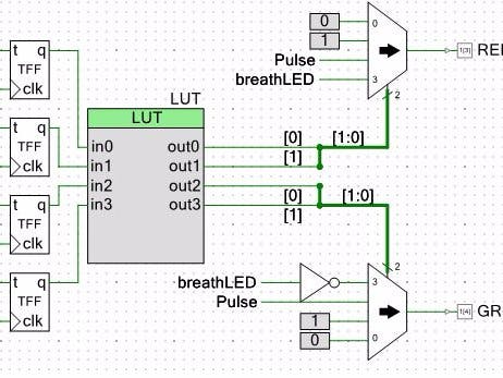
LUTTo decode each combination as a command I used a Look Up Table (LUT), this block allows to control what happens with each input combination.
To configure the LUT, you just need to click the bits to get the output desired for each combination.
The configuration of the outputs I chose is driven to a MUX (Multiplexer), this block allows to control multiple signals at the same time (so the LUT outputs are split into two pairs). With a 2-bit signal for each MUX, I choose the desired output for the RED and Green Pin. (Don't worry about the wires with only names for now.)
Notice the wire grows thicker when it connects to the MUX: this means it is a bus (more than one cable). To merge wires into buses, they need to be configured individually by right clicking each and selecting Edit Name and Width.
In the dialogue, a name can be added to each wire (must be done individually), and an index Bit can be selected. For each bus entering the MUX, we need a bit [0] and [1] (making a two bit bus):
To clean up the wiring between the blocks, the Names come in very handy. If a cable is given the same name in two different places (not physically connected), they will work as if they were connected:
Notice the breath LED and Pulse LED wires also appear on both MUXs; this way the same signal is used in both places in a very clean way.
Hope you like it! The Breathing LED was taken from Mark Ainsworth's Breathing LED!


Comments
Please log in or sign up to comment.