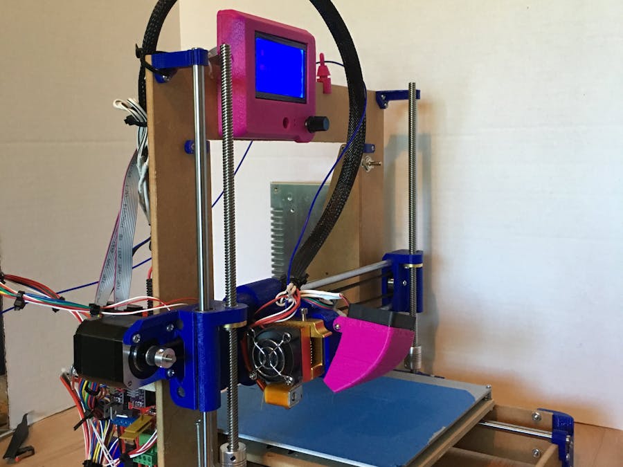
Bill of Materials is here. This is an inexpensive, but nicely functioning and robust 3D printer. I've made it for around $250. This will use an Arduino Mega and a RAMPS board.
You do need access to a 3D printer and a CNC if you are going to hit that price target. In order to build this machine you first cut the frame using a CNC. Alternatively from the vicious1.com site, there is a linked site that does produce nice high quality frames and parts bundles that you can order.
I believe it's more fun to build it all myself.
Once the frame is cut, you need to print out all the parts for the printer. Yes, that does mean you need a 3D printer to build this one. I just put the 3D print head on the CNC I had finished up previously.
Once the parts are printed, use the pictures on the provided web site (or in the gallery) to put all the pieces together.
In the case that you get stuck, post a comment here or in the forums on the vicious1.com website and those of us that have built this will help you out.
Build Notes:Prep the thermistor in the heated bed a day before assembly!
- Put bearings in all the pieces first. 1 bearing in each piece for the bed, 2 in all the rest except for the piece that holds the extruder which gets 3 (two on top, one on bottom).
- Put the end stop screws and end stops onto the plastic pieces. Pictures on the web site are adequate to see how that works. Pictures in the gallery are also probably fine.
- Put bearings in the plastic pieces. Pictures are adequate again.
- Solder wires onto end stops.
- Assemble the frame (corners and motor blocks and gantry) – Check for square
- Put motor mounts and pulley for the bed on the frame.
- Put the plastic piece that holds the timing chain on the bed. * Make sure that it aligns with the motor and pulley pieces. *
- Put the bearings on the bed.
- Put the end pieces on one end of the rods for the bed.
- Put the bed on the rods.
- Other end pieces on those same rods.
- Put on all the stepper motors
- Put the bed on the frame – check for square
- Build the x axis. – this uses the longest two rods into the plastic pieces and the carriage onto the rods. Put the timing chain on at this point too as it will be easier. Make sure the brass nuts are also put on at this point.
- Put the top of the y axis rods on the frame if you didn’t already.
- Put the x axis on the y axis rods. Put the y axis rods into the mounts at the top of the gantry, slide them up and then down into the motor mounts at the bottom.
- Slide the threaded rods down through the brass nuts and lock them into the steppers. Check for square.
- Bottom timing chain – set the end stop screw lengths now. make sure that they touch at the appropriate points.
- Route wires
- Mount power supply and ramps
- Mount extruder (and wire it if necessary)
- Place headed bed
- Plug in wires
- Power up and initial movement test — home it.
- Wire cleanup.
- Print/install boxes, covers, and wire ties as desired.
For the thermistor in the bed I used a high temperature silicon gasket compound and let it dry overnight. Do this in advance. I also wired in a power switch for the whole unit. I recommend doing this as well.
Since I have an MPCNC, I put two 8 pin DIN circular plugs on the extruder (one of the plugs for extruder power, the other plug for two fans and the thermistor) – This lets me move the extruder back and forth with minimal effort. I cut a wooden block and mounted the DIN’s into that and glued it to the frame next to where the ramps is mounted in order to facilitate easy transfer back and forth.
The mk3 bed uses #4 screws and not #6. Get one inch ones.
The wire bundle I have is pretty big. You MAY want to trim a long section of the stepper wires out if you don’t like large bundles. I don’t mind and I left them.
I recommend using shrink tube on all connections when you solder them. I usually run my printer through a Raspberry Pi using repeater server and if you do the same, you may need to flash the speed down to 128k baud from 250k.
Finally, I decided that I needed a bit more light for the printer. I used another toggle switch, a couple feet of strip LED's and glued it along the inside of the gantry. There's plenty of power available from the RAMPS board and basic power supply that I had, so just wire into one of the existing 12v outputs to power the lights.
If you want a bit less work, look at Ryan's web site and order parts from there.


_wzec989qrF.jpg?auto=compress%2Cformat&w=48&h=48&fit=fill&bg=ffffff)


Comments
Please log in or sign up to comment.