- Power supply 3 - 5.5 V DC
- Humidity range: 20%~90%RH (32-125ºF (0-50ºC) compensation).
- Temperature measuring range: 32-125º F (0-50ºC).
- Humidity measurement accuracy: ±5.0%RH.
- Temperature measurement accuracy: ±2.0degree.
- 1sec max sampling rate
- low power consumption.
- Size:23X12X5.5mm
- Power supply 3 - 5.5 V DC @2.5mA
- Humidity range: 0%~90%RH (-40 to +125ºF (-40 to +50ºC) compensation).
- Temperature measuring range: -40 to +125ºF (-40 to +50ºC).
- Humidity measurement accuracy: ±5.0%RH.
- Temperature measurement accuracy: ±0.5 degree.
- 2sec max sampling rate
- low power consumption.
- Size:23X12X5.5mm
The DHT11 (or DHT-11) uses a proprietary 1 wire communication protocol. According to the datasheet timing must be precise.
Data transmission is initiated by pulling the data bus low for about 18 ms and keep it HIGH for about 20-40 μs before releasing it. Subsequently, the sensor responds to the data request by pulling the data bus LOW for 80 μs followed by 80 μs of HIGH. Data is sent in packets of 40 bits (5 bytes) via the data line with the most significant bit at the beginning.
Data is transmitted in the following order:
- Byte 1: The integer part of the humidity reading.
- Byte 2: The decimal part of the humidity reading (Always reads 0 on DHT11).
- Byte 3: The integer part of the temperature reading.
- Byte 4: The decimal part of the temperature reading (Always reads 0 on DHT11).
- Byte 5: Checksum data ( lower 8 bits of the sum of bytes 1-4).
Data can be displayed as (Integer part).(Decimal part) For simple calculations, only the integer part is typically required.
Transmission of '0' & '1' is done by varying the width of the pulse.
- '0' is represented by holding the data bus HIGH for 26-28μs
- '1' is represented by holding the data bus HIGH for 70μs
A delay of 50μs(LOW) is introduced before any new data bit is transmitted. After transmitting the last data-bit, the data line is held LOW for 50μs and released.
PinoutPin Name Description
1 VCC Power supply 3 - 5.5 V DC
2 DATA Serial data output
3 NC Not connected
4 GND Ground
Important: To prevent random data errors, connect a 10K resistor between the DATA and VCC pins.
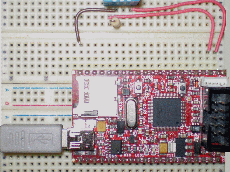
WiringConnect the sensor to the Pinguino as shown below
DHT11 Pinguino
Pin 1 Vcc
Pin 2 Any digital pin
Pin 4 Gnd


Comments
Please log in or sign up to comment.