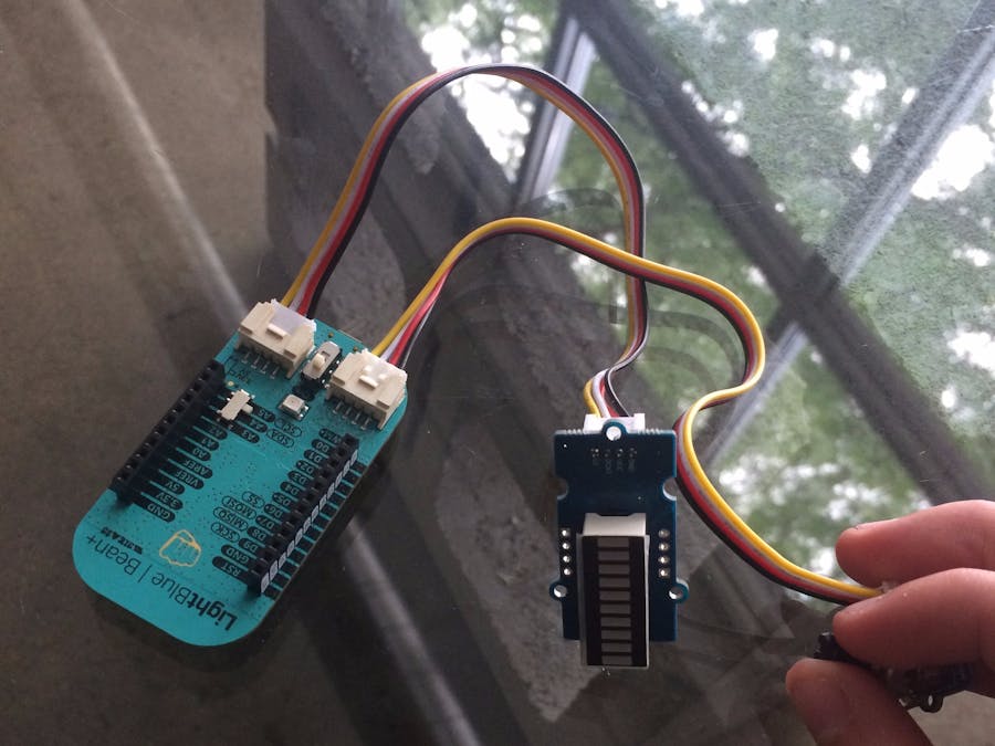
Here at Punch Through, we are so excited to have shipped the Bean+ and are looking forward to seeing all the neat projects people build with it. A few of people have mentioned that they want some guidance on how use the two Grove connectors on the Bean+ -- so I built this project to help get people started!
The Grove SystemLet's talk a little bit about the Grove system provided by SeeedStudio. Grove components are kinda like the electronic legos of the maker community. A wide variety of components are offered from sensors & UI pieces to wireless communication. They take care of all the hard stuff and provide an easy to use interface for incorporating Grove into your projects.
Because each component is a little different, I recommend reading up on each piece before using it. The have a great wiki page here. Be sure to note the pin connections and how they will need to be modified to run on the Bean+. A lot of the provided example sketches will be configured for running on a different device so be sure to make appropriate modifications. The pins used for Grove on the Bean+ are (A2/A3) for the left connector and (A4/A5) for the right connector. Some components such as the LED Bar use both the clock and data input pins while others only use one in the case of the Rotary Angle Sensor. Without having the pins defined in the correct way, your code will not work as expected.
For example, if the Rotary Angle Sensor is connected to (A2/A3), the higher pin, A3, is used to send the angle reading back to the device while the A2 pin is not connected. So, if your code defines the input pin for the Rotary Angle Sensor to be A2, you won't get any angle reading back from the sensor. Also, the same goes for components that use both the pins like the LED Bar. If the clock pin is defined to write to the data input and data pin defined to write the clock input, the LED Bar will not work. Anyways, I think I made my point.
Building itNow, time to get building. Switch the operating voltage on the front of the Bean+ from 3.3V to 5V in order to better drive the LED bar. Take the Grove rotary angle sensor and plug in the jumper cable and hook it up to the left Grove connector, marked (A2/A3). This is important, because we will need to match how the pin input and output are defined in the code later on. Then, do the same thing for the Grove LED bar and the right Grove connector, marked (I2C). How easy was that? No soldering required!
The codeOnto the code, programming the Bean+ will require you to install one of our Bean Loaders available here. If working from a desktop, platform you will also need an Arduino IDE installed, available here. Once you have that setup, you will need to download and add the library for the Grove - LED Bar, available here. Whoofda. I know, we are almost there, I promise -- because all that's left is to copy and paste the provided code into the editor, compile, and program the Bean+!


Comments
Please log in or sign up to comment.