Living in a 7 member family is difficult, especially when there are only 2 women to run the house hold. Due to immense workload in the house my mother and grandmother were unable to juggle between different works. if they were in the kitchen working, the water geyser in the bathroom(which we as young kids would forget to witch off) would short, emitting large amount of smoke. Or for example during Navratri the holy Garba(a lamp burnt during the hindu festival of navratri) would spontaneously start a fire burning the adjacent mat with it, Or something would go off in the kitchen when they were busy attending to guests. Living in a Hot and humid country like India, using LM-35 to detect a fire/smoke would not be appropriate as these things didnt exactly generate fire but emitted smoke and also the average temperature is anyway 35 degree celcius. So I came u with an idea that would specifically alert my family when something like this happened, and so with that was born my idea to make a smoke detection sensor
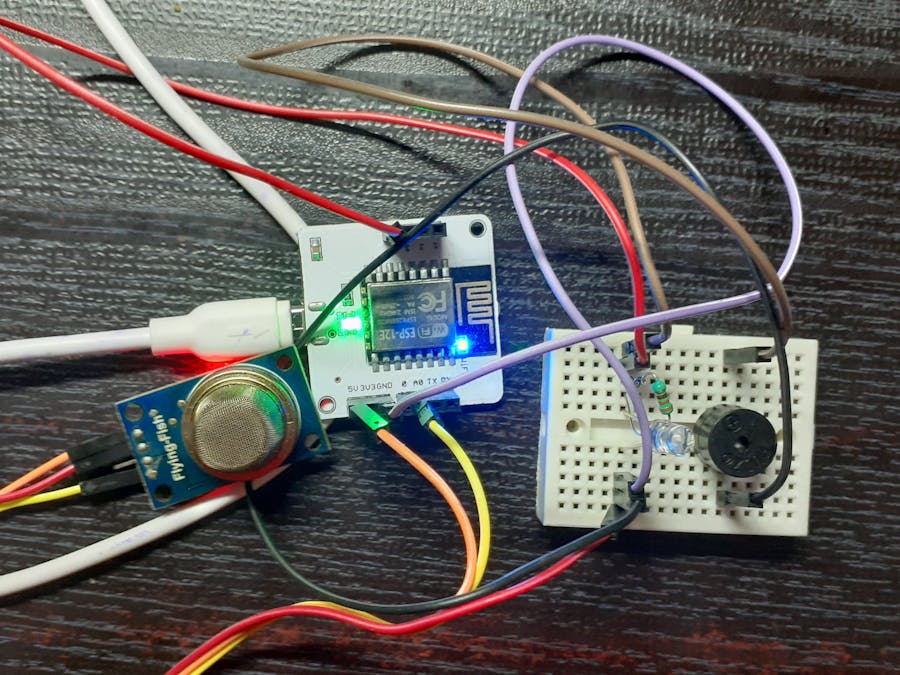
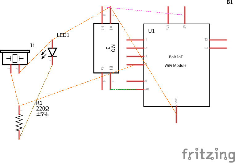
2. HARDWARE SET UP2.1 CONNECTING LED AND BUZZER
STEP 1: Insert the LED into the breadboard
STEP 2: Insert The Resistor in the bread board adjacent to the positive end of LED
STEP 3: Insert the Piezo electric Buzzer Parallel to the LED
STEP 4: Connect the negative end of LED to the Ground (GND)of BOLT module
STEP 5: Connect the open end of resistor to port 4 of BOLT module
STEP 6: Connect the negative end of buzzer to the negative end of LED with the help of jumper wire
STEP 7: Connect the positive end of buzzer with positive open end of resistor with the help of jumper wires
2.2 CONNECTION MQ2 SENSOR
2.2.1 ABOUT MQ2
The Grove - Gas Sensor(MQ2) module is useful for gas leakage detection (home and industry). It is suitable for detecting H2, LPG, CH4, CO, Alcohol, Smoke or Propane. Due to its high sensitivity and fast response time, measurement can be taken as soon as possible. The sensitivity of the sensor can be adjusted by potentiometer.
The MQ2 has 4 pins(from right to left)
1. VCC(Supply Voltage Pin)
2. GND(Ground output pin)
3. D0 (Digital Output pin)
4. A0(Analog output pin)
2.2.2 CONNECTION
STEP 1: Connect The VCC pin of MQ2 to 5V pin of BOLT module
STEP2: Connect The ground(GND) pin to negative end of LED(as negative end of LED is connected to GND port of BOLT module)
STEP 3: Connect the Analog(A0) pin of MQ2 to analog port of BOLT module
YOUR HARDWARE CONNECTIONS ARE READY!
Log into https://cloud.boltiot.com/ and follow the below instructions
Special thanks to
Vinayak Joshi Sir
Mr Pranav Pai Vadnekar


Comments
Please log in or sign up to comment.