


Hardware components | ||||||
 |
| × | 2 | |||
| × | 2 | ||||
| × | 1 | ||||
 |
| × | 1 | |||
 |
| × | 1 | |||
We made some Pmod PCBs from JLCPB for the RN4871 BLE module samples that we had, you can check details on this other post.
The Pmod breakouts for the RN4871 have available a couple of GPIOs and we thought of trying to control them over BLE using the remote command feature.
The Remote Command mode provides a method to enable stand-alone implementation without host MCU for the remote device. A local device can use the Remote Command mode to get access to the remote device (module), access and control all its analog or digital I/O ports. All application logics are performed locally without the remote device's interferences. Therefore, there is no required programming or application logic to run on the remote device. By this method, we can make the remote device extremely easy to implement with the lowest cost.
The modules we got have available 2 digital pins, I have not checked any details on the RN4870 but it looks promising having more I/O pins than the RN4871.
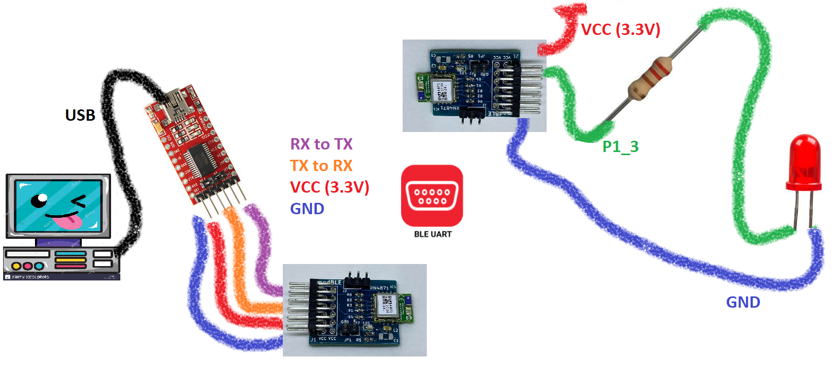
We connected P1_3 on one of the RN4871 to an LED to test toggling it from the other RN4871.
We did some configuration using a USB to Serial converter, if you are planning to use one of these make sure it support 3.3V otherwise you will damage the modules.
The idea is to have a local BLE module, in this case controlling a GPIO of the remote BLE module. To get into remote mode, both devices need to be connected and secured. Check our previous post on how to configure the serial connections to access the configuration of the RN4871.
The default configuration is having Authentication = 2.
NoInputNoOutput – RN4870/71 as responder automatically confirms passkey. The remote peer device as initiator manually confirms or automatically confirms passkey.
Aditionally, the UART transparent service is active by default Services = C0.
I am not sure if this step is necessary, but I changed the pin code on both devices with command SP, 123456. Both modules have the same PIN.
And now both modules have Authentication = 1.
DisplayYesNo – RN4870/71 as responder displays and automatically confirms passkey. The remote peer device as initiator displays and manually confirms or automatically confirms passkey.
The BLE connection can be initiated from either module, F command can be used to scan the available BLE devices.
Scan command can be skipped if the address is known, the connection is done with command C, 0, address.
Notice the SECURED message.
Once the secured connection and UART transparent services are set in both devices, is now time to fire the remote command (on local device).
Command ! controls remote command feature. It expects one parameter, either 1 or 0. If the input parameter is 1, then remote Command mode is enabled and the device automatically enters Remote Command mode. When in Remote Command mode, the command prompt CMD> changes to RMT>. Command ! is only effective under the following conditions: • Both local and remote devices support UART Transparent feature. • The two devices are already connected and secured.
On the local device using the serial terminal the !, 1 remote command is triggered.
Notice on the remote device, a RMT_CMD_ON message is displayed, meaning the local device is now connected to the remote device.
We are now attempting to change P1_3 state on the remote device. This pin has no default function but other pins have specific function that can be changed. Refer to table 2-8 from the datasheet.
We left the default configuration options for this example.
To change the output of the digital pins the |O command is used (pipe symbol not i, not I, not L, not 1).
Command |O sets the output value of the digital I/O ports. It expects two input parameters. The first parameter is the bitmap of digital I/O ports that are affected by this command; the second parameter is the output value in the bitmap.
To choose the specific pin, again refer to Table2-11 on the datasheet. The first parameter is the pin, in this case P1_3 is 10 (hex). The second parameter is the output value, 10 (hex) also sets the pin P1_3 to HIGH. To clear the pin send 00 as the second parameter.
Also, both pins P1_2 and P1_3 can be set on the RN4871 with a single |O command, like this: |O, 18, 18 and clear both |O, 18, 00, or mix their states |O, 18, 10 and |O, 18, 08.
In the following image, the local device is toggling the LED of the remote device, take a look at the command sequence: |O, 10, 10 to set the LED and |O, 10, 00 to clear it. The remote module answers back AOK for each command succesfully executed.
We'll think about a project with this nice feature of not needing a host MCU and just use two RN4871 modules, unfortunately the remote mode only works between them.
This module also supports a script mode
In a typical use case, a host MCU uses ASCII commands over UART to control and exchange data with the RN4870/71 BLE module. For simple applications, such as a sensor or beacon broadcaster, a host MCU may not be necessary.
The main functionalities of scripting are achieved by executing ASCII commands that are the same as those via UART interface.
More on script mode on another post!


Comments
Please log in or sign up to comment.