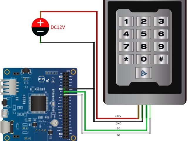
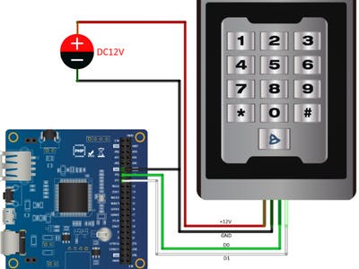
The PHPoC Blue is interfaced with a RFID card reader through the Wiegand interface. When a RFID card is tagged to the RFID card reader, it sends the card information to the PHPoC Blue through the Wiegand interface.
Wiegand ProtocolThe Wiegand interface is a de-facto standard which gets RFID card data through the 2 signal wires - D0 and D1. (Refer: https://en.wikipedia.org/wiki/Wiegand_interface)
The Wiegand Protocol uses two data lines - Do and D1. The D0 represents "0" and the D1 represents "1" and both are active LOW. It is a bit stream including data pulse widths and data intervals. The data will be placed at the timing of the data pulse width and there's no data during the data intervals.
The bit stream is composed with 26 bit data - two parity bits and 24 data bits. The parity bits are placed in the first and last position. The first bit is an even parity of former 12 bits and the last bit is a ODD parity of the latter 12 bits.
The following is a screen of oscilloscope which displays the wiegand signals.
1. PHPoC Blue with a USB WiFi dongle
2. RFID reader (it is from here)
3. DC +12V Power Supplier
4. Jump wires
5. Smart device (Smart phone or Smart pad)
Software ImplementationThe PHPoC Blue's Hardware timer pins(HT0 and HT1) are connected to the RFID reader's D0 and D1 pins respectively.
It counts the duration between edges incoming from the HT0 and HT1. And it makes binary bit streams by using the duration data for each ports. It can make only "0" bit stream with the HT0 and only "1" bit stream with the HT1. But we can calculate "1" data and "0" data by using the rest period from each the HT0 and HT1 respectively.
Now we have two bit stream from the each port. We can get real data if we remove the duplicated data. The last thing we have to do is calculate the parity if there is any error in the data frame.
Demonstration


Comments