

Hardware components | ||||||
_PnKPri8a6q.jpg?auto=compress%2Cformat&w=48&h=48&fit=fill&bg=ffffff) |
| × | 1 | |||
 |
| × | 1 | |||
 |
| × | 1 | |||
| × | 1 | ||||
| × | 1 | ||||
| × | 1 | ||||
 |
| × | 1 | |||
 |
| × | 1 | |||
 |
| × | 1 | |||
 |
| × | 1 | |||
 |
| × | 1 | |||
 |
| × | 20 | |||
| × | 1 | ||||
| × | 1 | ||||
| × | 1 | ||||
| × | 1 | ||||
Software apps and online services | ||||||
 |
| |||||
Hand tools and fabrication machines | ||||||
 |
| |||||
 |
| |||||
[ENG] I prepared the project description in both English and Hungarian.
GO TO ARDUINO PROJECT HUB PROJECT
[HUN] A projekt leírását elkészítettem angolul és magyarul is.
UGRÁS A MAGYAR LEÍRÁSHOZ (ARDUINO PROJECT HUB)
UGRÁS A MAGYAR LEÍRÁSHOZ (HACKSTER.IO)
━━━━━━━━━ENGLISH VERSION━━━━━━━━━PROJECT STORYI started working with the Arduino in February 2022, when I decided to write my thesis on this topic for my university degree, namely by building a concrete smart home. Since then, the thesis has been completed and my interest in Arduino has been rekindled, so I have been looking for my next possible hobby project.
On both my company laptop and my own private laptop, I was getting annoyed by the number of times I had to type in passwords, which are of course long and include lower case, upper case, numbers and special characters. So I decided to find a solution that would eliminate the need to type the password over and over again, while maintaining the same level of security, or even higher. That's when I came across RFID as a possible solution.
Another argument in favour of RFID was that I use an RFID card at work to access the building and I can only visit certain rooms with this card (provided I have the authorisation), so I can lock and unlock Windows with this one card.
INTRODUCTIONAfter researching on the internet, it became clear that this was the way I wanted to go for the project, but I also had concerns about security. Similar RFID projects can be found all over the web, but they did not deal with encryption or security increasing. I have completely rejected password solutions burned into program code or saved in simple txt files used by REGEDIT.
After a lot of brainstorming, I came up with two possible paths:
- To make RFID access more secure, I use an Android application that can send the user's password to the Arduino via Bluetooth, with AES encryption on the sending side and AES decryption on the receiving side. In addition, on the Arduino side, I incorporate additional mechanisms to increase security: in case of a bluetooth connection being broken, the password is always invalidated and deleted; if no one sits in front of the machine for a certain period of time, the system automatically locks the account; in case of continuous work, continuous bluetooth connection and active logged in account, a password validity period is also defined, which, when expired, the system will only work properly if the password is sent to the Arduino again via the application.
- The second version is completely the same as the first, except that it does not include two-sided AES encryption and decryption.
The choice between the two versions was essentially (unfortunately) simple. The memory (I didn't want to use a memory card) and speed of the Arduino Micro didn't allow for the addition of AES encryption to the program code. When looking at the version without encryption, I found that using encryption would not have made the system more secure, as the password would have had to be entered in the application anyway. The use of AES would have only increased the security level in the communication channel (bluetooth), however, I could not consider this as a maximization of security due to the decryption of AES.
Once the direction was chosen, the operational elements and functions of the system were defined:
- Only one RFID card is accepted as valid, both when locking the user account and when logging in.
- After each card reading, the scanned card data (UID) is released by the system and is not stored. Only the UID of the master card (which is used to operate the system) is burned into the program code.
- The application is able to connect to the HC-06 bluetooth module and to send the password given by the user.
- If the password expires, if there is no bluetooth connection or if the password is not correct, the access will fail. Therefore, in order to be able to perform an access, the following must be present: valid password, active bluetooth connection, valid, correctly entered password.
- To lock the account with an RFID card, only the master card is needed, with the same UID as the card burned into the program code.
- The device can also perform automatic locking using the ultrasonic distance sensor (HC-SR04) and the potmeter. The potentiometer is used to set the distance in centimetres within which, if nothing is detected by the range finder and the system status is an entered session, the account is automatically locked within 10 seconds. The countdown will be interrupted in two cases: when the potentiometer is set to a position where the rangefinder sensor is sensed again within the set value (distance), or when the rangefinder sensor is sensed again within the original, previously set value of the potentiometer.
- All information is displayed on the OLED display: the fact of entry and exit, the value of the sensing distance in centimetres modified by the potentiometer, the time remaining until automatic lock-out in seconds.
- The device is also able to wake up the system from sleep mode, combined with the login, provided that the last system status is 'locked account', the bluetooth connection is active and the password is correct. For this feature to work correctly on other devices, it may be necessary to modify the program code to optimize it for that device (modify the delay() commands in the login function to the appropriate delay time.)
Below, I will describe the tools used in the project, their exact wiring and mention any important information relevant to the project.
Arduino MicroThe Arduino Micro is a microcontroller card based on the ATmega32U4, developed in collaboration with Adafruit.
It has 20 digital input/output pins (7 of which can be used as PWM outputs and 12 as analogue inputs), a 16 MHz crystal oscillator, micro USB connection, ICSP header and reset button.
Connecting the MFRC522 via SPI: (MFRC522 -> Arduino Micro)
- SDA -> SS
- SCK -> SCK
- MOSI -> MOSI
- MISO -> MISO
- IRQ -> NOT CONNECTED
- GND -> GND
- RST -> 5
- VCC -> 3.3V
Connecting the HC-06 bluetooth module: (HC-06 -> Arduino Micro)
- RXD-> TXD
- TXD-> RXD
- GND -> GND
- VCC-> 5V
The RX and TX legs of the HC-06 bluetooth module are NOT 5V tolerant, however for proper operation it is sufficient to install a 5V - 3.3V voltage divider for the RX leg only, which I implemented with a 10kΩ and a 20kΩ resistor.
To check and calculate whether the correct resistors have been used in the design of the voltage divider, you can use the following calculator:
Why is it important to use the right voltage divider? In the initial phase of my project, I successfully forgot to install the necessary voltage divider for the HC-06 module, so I baked one, the result of which is nicely shown in the video below. (The LED flashes in a way not described in the documentation, the module could not be found with any tool, so connection/pairing was impossible.)
The HC-SR04 distance sensor moduleConnecting the HC-SR04 distance sensor module: (HC-SR04 -> Arduino Micro)
- VCC-> 5V
- TRIG -> 8
- ECHO -> 7
- GND -> GND
The main parameters of the display I use:
- 128x32 pixel resolution
- 0.91" Ø
- I2C communication
- SSD1306 driver
Connecting the OLED display: (OLED -> Arduino Micro)
- GND -> GND
- VCC -> 5V
- SCL -> 3
- SCA -> 2
Connecting the potentiometer: (Potentiometer -> Arduino Micro)
- VCC - 5V
- SIGNAL - A0
- GND - GND
A simple LED is built into the device to indicate the current system status (session logged in or logged out)
It is also recommended to use a resistor when connecting the LEDs to significantly increase the lifetime of the LEDs. One of the most accepted and widely used resistors for connecting LEDs is the 220Ω resistor. I have used it for wiring.
Connecting the LED: (LED-> Arduino Micro)
- Cathode leg (shorter) - GND
- Anode leg (longer) - 13 (via 220Ω resistor)
I needed a compact device, a box, to contain the project. Possible solutions included 3D printing and an assembly and utility box.
Since I do not have a 3D printer or the design skills to use one, and considering the cost of 3D printing, I passed on this option as it would have significantly increased the overall production cost for this small project.
Utility boxes seemed like a good solution based on their availability and price, however I couldn't really find a suitable size, shape and design, so I left this option as a backup.
Okay, but what then? I remembered that I had an old but no longer working 8-port TP-Link switch (TL-SF1008D) lying around the house somewhere, which might be suitable for this project. I found it, so I set about dismantling it. After preliminary planning and measurements, I came to the conclusion that this box could be used, even if it was difficult, and that the project hardware could be placed inside.
I had to make some modifications to the switch box, which were as follows:
- Complete removal of the internal plastic patents and the UTP connector module.
- Shortening of the plastic conductors transmitting the light of the internal indicator lights.
- Removal and gluing of the original power supply location.
- Drilling of 3 holes for the distance sensor (acrylic bracket (2 pcs), wires (1 pc)).
- Drilling 1 hole for micro USB connector for microcontroller.
- 1 drilling for the potmeter.
- I placed 2 feet on the front bottom of the box, on which I also attached rubber shock absorber pads.
Examining the design of the switch, I decided that the back of the switch would be the front of the project box, as it originally had a long slot to accommodate the OLED display and glue the hobby glass plate. To fix the devices in the box, I used superglue and glue gun, depending on what, how and where I needed to fix.
After finalizing and assembling, I sprayed the whole device with universal black paint.
The necessary libraries will be imported:
#include <AnalogPin.h>
#include <Keyboard.h>
#include <SPI.h>
#include <Wire.h>
#include <MFRC522.h>
#include <SoftwareSerial.h>
#include <Ultrasonic.h>
#include <Adafruit_SSD1306.h>
#include <U8g2_for_Adafruit_GFX.h>
AnalogPin (v0.2.6 - RobTillaart):AnalogPin is an Arduino class that adds noise filtering and smoothing to analogRead(). It smoothes and corrects the 'value jump' that can be detected during read and display.Keyboard (v1.0.2):allows 32u4 or SAMD based cards to send keystrokes to a connected computer via the native USB port.SPI:This library allows communication with SPI devices, using the Arduino control device. This library is included with all Arduino platforms (avr, megaavr, mbed, samd, sam, arc32), so you do not need to install the library separately.Wire:This library allows communication with I2C/TWI devices.MFRC522 (v1.4.10 - Miguel Balboa):Arduino library for MFRC522 and other RFID RC522 based modules.SoftwareSerial:The SoftwareSerial library allows serial communication on other digital ports of the Arduino card, with software replication.
On Micro cards, not all digital ports support switching interrupts, so only the following can be used for RX: 8, 9, 10, 11, 14 (MISO), 15 (SCK), 16 (MOSI).
Ultrasonic (v3.0.0 - Erick Simoes):The library is designed to improve resource efficiency and simplify access to data. This library is minimalist, reducing code execution, validation and unnecessary use of global variables, favouring smaller data types.Adafruit_SSD1306 (v2.5.6 - Adafruit):This is a library of monochrome OLEDs based on the SSD1306 drivers. These displays use I2C or SPI for communication.U8g2_for_Adafruit_GFX (v1.8.1 - Oliver):Adds the U8g2 text drawing engine to all Adafruit GFX based Arduino libraries.
#define LED 13We define our LED as being connected to digital port 13.
ConstructorsAnalogPin Apin(A0);
U8G2_FOR_ADAFRUIT_GFX u8g2_for_adafruit_gfx;
MFRC522 mfrc522(SS, 5);
MFRC522::MIFARE_Key key;
SoftwareSerial EEBlue(11, 10);
Ultrasonic ultrasonic(8, 7, 68000UL);
Adafruit_SSD1306 display = Adafruit_SSD1306(128, 32, &Wire, 13, 400000UL, 100000UL);All the necessary classes are instantiated with the appropriate constructor. For the ultrasonic distance sensing sensor, 68000UL is a 68 thousand microseconds (68 milliseconds) timeout, a latency value that is the final result of fine-tuning my own project. The default value of this parameter is 20000UL.
One oddity in the display constructor is that I have specified the digital port of the connected LED as the RESET_PIN parameter. The reason for this is that without it the display did not work properly. It would light up and then go dark on every startup. Sending a 'high' value with digitalWrite(LED, HIGH); in the setup() section of the code (see below) successfully solved the problem with the display.
Global variablesconst char card1[32] = "EB1CEFFC";
const long passwordExpireInterval = 3600000;
char str[32] = "";
String readid, password = "";
byte readCard[4];
byte distance, i, lastx, x = 0;
byte isLogged = 0;
unsigned long lastPasswordCheck, lastPotChange, start = 0;The next step is to declare and initialise the global variables. The UID of the master RFID card is burned in the variable card1 (constant). The two most important variables that need to be explained are isLogged, which stores whether the current state is a logged in (1) or logged out (0) state, and passwordExpireInterval (constant), which specifies the interval (milliseconds) at which the password expires, even if you are otherwise logged in all the time during that interval.
The other variables are used to scan the card, password, distance, and to properly service the operation.
Setup()void setup() {
display.begin(SSD1306_SWITCHCAPVCC, 0x3C);
u8g2_for_adafruit_gfx.begin(display);
display.clearDisplay();
display.display();
pinMode(LED, OUTPUT);
pinMode(11, INPUT);
pinMode(10, OUTPUT);
digitalWrite(LED, HIGH);
Serial.begin(57600);
SPI.begin();
mfrc522.PCD_Init();
Keyboard.begin();
EEBlue.begin(9600);
}In setup(), all the necessary settings are made. As I mentioned earlier, for proper operation I needed to place an initial 'high' state for the LED here, so that the display does not turn off after the system is started. (digitalWrite(LED, HIGH);)
setPassword()void setPassword() {
if (EEBlue.available() > 0) {
password = EEBlue.readStringUntil('\n');
}
}The setPassword() function is used to read the password sent via bluetooh and store it in the password variable. It processes the sent string to the end of the line (new line).
resetPassword()void resetPassword() {
if ((millis() - lastPasswordCheck) >= passwordExpireInterval) {
password = "";
lastPasswordCheck = millis();
}
}Each time the resetPassword() function is called, it checks if it is necessary to reset the password and retrieve it through the application. The password expiration time is set in the passwordExpireInterval variable, which cannot be changed during program execution. Currently the constant is set to 3600000, which corresponds to 60 minutes.
According to the logical check, it is necessary to delete the password if the difference between the current time (millis(): time elapsed since the device was started) and the last password check (lastPasswordCheck) is greater than or equal to passwordExpireInterval (password expiry time). For each deletion, it is of course necessary to set the time of the last deletion/check.
loginCommand()void loginCommand() {
Keyboard.press(KEY_LEFT_CTRL);
Keyboard.press('a');
Keyboard.releaseAll();
delay(400);
Keyboard.press(KEY_ESC);
Keyboard.release(KEY_ESC);
Keyboard.print(password);
Keyboard.releaseAll();
delay(100);
Keyboard.press(KEY_RETURN);
Keyboard.release(KEY_RETURN);
isLogged = 1;
digitalWrite(LED, HIGH);
message();
}The loginCommand() procedure implements the login to Windows, i.e. the manipulation and reproduction of the keyboard keystroke.
The first 4 commands can delete erroneously typed characters in the password field by using the 'select all' (CTRL+A) key manipulation to select all previously typed characters. With the first and last delay(400); command, it was possible to wake up a sleeping system and execute the entry.
This is followed by 'typing' the stored password and pressing ENTER. At the end of the login, the current status is set to 'logged in' (isLogged = 1;), the LED is turned on and the corresponding message is displayed on the oled display (UNLOCKED).
winLock()void winLock() {
Keyboard.press(KEY_LEFT_GUI);
Keyboard.press('l');
Keyboard.releaseAll();
isLogged = 0;
digitalWrite(LED, LOW);
message();
}The winLock() method locks Windows. This can be done by manipulating the lower left Windows key and the letter 'L' together.
After locking, the status will be set to 'logged out' (isLogged = 0;), the LED will be turned off and the corresponding message will be displayed on the oled display (LOCKED)
message()void message() {
display.clearDisplay();
u8g2_for_adafruit_gfx.setFont(u8g2_font_doomalpha04_tr);
if (isLogged == 0) {
u8g2_for_adafruit_gfx.drawStr(0, 32, "LOCKED");
} else {
u8g2_for_adafruit_gfx.drawStr(0, 32, "UNLOCKED");
}
display.display();
delay(1000);
}The message() function is responsible for writing the appropriate message to the oled display each time you log in and lock. The first two steps of the function clear the current contents of the display and set the font to use.
After positioning and specifying the message, the message is printed (display.display();) and a delay of 1 second is applied (delay(1000);)
getID()void getID() {
if (!mfrc522.PICC_IsNewCardPresent()) {
return;
}
if (!mfrc522.PICC_ReadCardSerial()) {
return;
}
for (int i = 0; i < mfrc522.uid.size; i++) {
readCard[i] = mfrc522.uid.uidByte[i];
}
mfrc522.PICC_HaltA();
}The getID() method is responsible for continuously scanning the RFID card and storing its UID. At the end of each run, it stops the scan by calling PICC_HaltA(); on our RFID instance (mfrc522).
It reads the UID of the RFID card being read into an array (readCard ) of type bytes, which are hexadecimal values.
arrayToString()String arrayToString()(byte array[], unsigned int len, char buffer[]) {
for (unsigned int i = 0; i < len; i++) {
byte nib1 = (array[i] >> 4) & 0x0F;
byte nib2 = (array[i] >> 0) & 0x0F;
buffer[i * 2 + 0] = nib1 < 0xA ? '0' + nib1 : 'A' + nib1 - 0xA;
buffer[i * 2 + 1] = nib2 < 0xA ? '0' + nib2 : 'A' + nib2 - 0xA;
}
buffer[len * 2] = '\0';
return buffer;
}The arrayToString() method is responsible for converting the UID of the scanned RFID card into a String type, because as I mentioned before, this identifier is only available in hexadecimal after the scan.
deleteCardInfo()void deleteCardInfo() {
for (int i = 0; i < mfrc522.uid.size; i++) {
readCard[i] = "";
}
readid = "";
}The deleteCardInfo() function deletes the UID of the scanned card each time it is run.
readDistance()byte readDistance() {
return ultrasonic.read(CM);
}In each case, the readDistance() method reads and returns the distance in centimeters detected by the ultrasonic distance sensor.
countDown()void countDown() {
if (start == 0 || i == 0) {
start = millis();
i = 11;
}
long last;
while (i > 0 && distance > x) {
last = millis();
distance = readDistance();
Apin.setNoiseThreshold(4);
x = map(Apin.read(), 0, 1023, 30, 200);
if (last - start >= 1500) {
display.clearDisplay();
u8g2_for_adafruit_gfx.setFont(u8g2_font_doomalpha04_tr);
u8g2_for_adafruit_gfx.drawStr(0, 32, "LOCKING IN");
u8g2_for_adafruit_gfx.setCursor(70, 32);
u8g2_for_adafruit_gfx.print(i - 1);
(i > 10) ? u8g2_for_adafruit_gfx.drawStr(85, 32, "sec") : u8g2_for_adafruit_gfx.drawStr(80, 32, "sec");
display.display();
i--;
if (i == 0) {
winLock();
distance = 0;
start = 0;
}
start += 1000;
last = millis();
}
}
distance = 0;
start = 0;
i = 0;
}The countDown() method is responsible for the complete implementation of the automatic countdown. The value stored in the variable I and specifies the number of seconds from which the countdown should start. (i-1)
In the case of a 10 second countdown, the value of I is 11 because this is how the countdown starts from 10 and how 0 is displayed at the end of the countdown. Overall, if we want to be strict, the code does not actually implement a 10-second countdown in this case, but rather a countdown of about 12 seconds. The reason is that the countdown only starts if our countdown is greater than zero, we are out of lock range (distance > x), and at least 1.5 seconds have elapsed since these two conditions have been met. This was necessary so that the countdown would not start immediately, but would have a delay.
The above logic test therefore also includes the exit condition that if the distance sensor detects within range again, it should abort the automatic lock. If no interruption occurs, the winLock() function is called, the Windows lock is done and all variables that serve the countDown() function are reset to their respective states and values.
During the countdown, we always show on the display how many seconds are left until the lock. The display of the 'centimetre' unit has also been optimised depending on whether the time remaining is in single or double digits.
loop()void loop() {
Apin.setNoiseThreshold(5);
x = map(Apin.read(), 0, 1023, 30, 200);
distance = readDistance();
if (distance > x && isLogged == 1) {
countDown();
} else {
if (lastx == x && millis() - lastPotChange > 2000) {
display.clearDisplay();
u8g2_for_adafruit_gfx.setFont(u8g2_font_doomalpha04_tr);
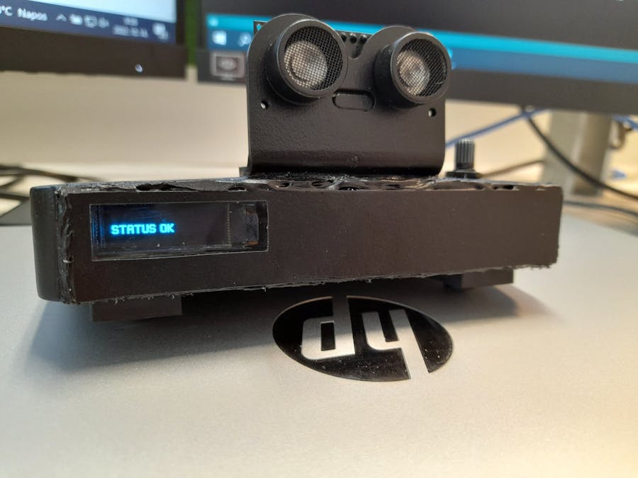
u8g2_for_adafruit_gfx.drawStr(0, 32, "STATUS OK");
} else if (lastx != x) {
display.clearDisplay();
u8g2_for_adafruit_gfx.setFont(u8g2_font_open_iconic_embedded_2x_t);
u8g2_for_adafruit_gfx.drawGlyph(0, 32, 0x0050);
u8g2_for_adafruit_gfx.setFont(u8g2_font_doomalpha04_tr);
u8g2_for_adafruit_gfx.setCursor(30, 31);
u8g2_for_adafruit_gfx.print(x);
if (x > 99) {
u8g2_for_adafruit_gfx.drawStr(55, 32, "CM");
} else {
u8g2_for_adafruit_gfx.drawStr(50, 32, "CM");
}
lastx = x;
lastPotChange = millis();
}
display.display();
}
getID();
readid = arrayToString(readCard, 4, str);
setPassword();
resetPassword();
if (password != "" && password.length() > 8 && readid == card1 && isLogged == 0) {
loginCommand();
} else if (readid == card1 && isLogged == 1) {
winLock();
}
deleteCardInfo();
}The loop() call implements the call of predefined functions and the execution of the program itself in the appropriate way.
At each step, the data measured by the range sensor and the potmeter is read. By examining this information and the status (isLogged), we determine whether we need to trigger the automatic lock or just decide whether we need to implement the entry or lock.
If we can't talk about automatic locking, we detect if the potentiometer is being rolled. If yes, the data read by it (lock limit in centimetres) will be shown on the display, if not, a simple 'STATUS OK' will be written on the display. Here again, the optimal display of text has been handled by specifying two or three digits for the scanned locking distance. To ensure a good user experience, a 2 second delay has been incorporated at the end of the potentiometer winding, so that the set distance is still shown on the display for an optimum amount of time.
To log in, the following conditions must be co-existence: the password must be at least 3 characters long, the UID of the scanned card must match the UID of the master card and the account status must be locked.
To be locked, the following conditions must be co-existence: the scanned card UID must be the same as the master card UID and the account status must be logged in.
ANDROID - MIT APPINVENTOR V2If the connection is successful and the password is sent, there is no confirmation in the app, but if the bluetooth connection fails, there is a feedback.
SUMMARYOf course, the finished tool is not the most perfect in every way, but as a hobby project I think it's worthy. The gluing of the hobby glass leaves something to be desired, but I couldn't use superglue to fix it because the test gluing showed that superglue would etch the glass. Finally, during the glue gun gluing, I tried in vain to smooth the glue, but after drying it took its final shape as shown in the picture. Of course, there are post-processing solutions to make it look more aesthetically pleasing, but I decided to leave this as a part of the project that I could definitely tie in.
I hope you liked the idea, the implementation and the description of the project. If you have any questions, comments or criticisms about anything, feel free to post them in the comments section below.
2022. februárjában kezdtem el foglalkozni az Arduino világával, amikor is eldöntöttem, hogy az egyetemi diplomám megszerzéséhez szükséges szakdolgozatomat ebben a témában, témakörben fogom írni, mégpedig egy konkrét okosotthon elkészítésével. Azóta a szakdolgozat elkészült, érdeklődésem az Arduino-val kapcsolatban pedig fellángolt, így kerestem a következő lehetséges hobbi projektet.
A munkavégzéshez használt, illetve a saját privát laptopomon is kezdett idegesíteni, hogy mennyiszer kell a jelszót begépelnem, amelyek természetesen hosszúak és tartalmaznak kisbetűt, nagybetűt, számot és speciális karaktert is. Így hát elhatároztam, hogy keresek egy olyan megoldást, amellyel meg tudom szüntetni a jelszó újra és újra begépelését, ugyanakkor a biztonság megmarad ugyan olyan szinten, vagy akár még magasabb is lesz. Ekkor találtam rá az RFID-ra, mint lehetséges megoldásra.
További érv volt az RFID mellett az is, hogy a munkahelyemen RFID kártyát használok az épületbe való bejutáshoz és bizonyos helyiségeket is csak ezzel a kártyával vagyok képes látogatni (feltéve, ha van hozzá jogosultságom), így ezzel az egy kártyával képes lehetek a Windows zárolására és feloldására is.
BEVEZETÉSAz interneten való kutatás után nyilvánvalóvá vált, hogy ez lesz az általam járni kívánt út a projekt megvalósítása felé, ugyanakkor aggodalmaim léptek fel a biztonságot tekintve. Hasonló RFID-s projektek megtalálhatóak szerte a weben, de ezek nem foglalkoztak sem titkosítással, sem a biztonság megtartásával, emelésével. A programkódba beégetett vagy a REGEDIT által használt, egyszerű txt állományokba mentett jelszavas megoldásokat teljes mértékben elvetettem.
Sok-sok brainstorming után két lehetséges járható út fogalmazódott meg bennem:
- Az RFID-s belépést biztonságosabbá teszem egy Android-os alkalmazással, amely bluetooth kapcsolaton keresztül képes megküldeni a felhasználó által megadott jelszót az Arduino felé, mindezt a küldő oldalon AES titkosítással, fogadó oldalon pedig AES visszafejtéssel. Továbbá az Arduino oldalán beépítek további, a biztonságot emelő mechanizmusokat: A bluetooth kapcsolat bontása esetén a jelszó minden esetben érvényességét veszti, törlésre kerül; Ha nem ül senki a gép előtt bizonyos ideig, akkor a rendszer automatikusan lezárja a fiókot; Folyamatos munkavégzés, folyamatos bluetooth kapcsolat és aktív, belépett fiók esetében is meghatározásra kerül egy jelszó érvényességi idő, amely ha letelik, a rendszer csak akkor fog megfelelően működni, ha az applikáción keresztül a jelszó újra megküldésre kerül az Arduino-nak.
- A második verzió teljes mértékben ugyan az, mint az első, annyi különbséggel, hogy nincs benne a kétoldali AES titkosítás és visszafejtés.
A két verzió közül való kiválasztás lényegében (sajnos) egyszerű volt. Az Arduino Micro memóriája (nem szerettem volna memóriakártyát használni) és sebessége nem tette lehetővé a programkód kiegészítését az AES titkosítással. A titkosítás nélküli verziót tekintve azt állapítottam meg, hogy a titkosítás alkalmazása nem tette volna biztonságosabbá a rendszer működését, hiszen az applikációban mindenféleképpen meg kellett volna adni a jelszót. Az AES alkalmazása csak a kommunikációs csatornában (bluetooth) emelt volna a biztonsági szinten, ugyanakkor az AES visszafejthetősége miatt ezt sem tekinthettem volna a biztonság kimaxolásának.
Az irány kiválasztása után definiálásra kerültek a rendszer működési elemei és funkciói:
- Csak egy RFID kártyát fogad el validnak a rendszer, mind a felhasználói fiók zárolásakor, mind a belépéskor.
- Minden kártyaolvasás után a beolvasott kártya adatát (UID) a rendszer felszabadítja, tehát nem kerül tárolásra. Egyedül a mester kártya (amivel működtethető a rendszer) UID-ja kerül beégetésre a programkódba.
- Az applikáció képes csatlakozni a HC-06 bluetooth modulhoz illetve megküldeni a felhasználó által megadott jelszót.
- Amennyiben a jelszó érvényességi ideje lejárt, nincs bluetooth kapcsolat vagy a jelszó nem megfelelő, a beléptetés nem valósul meg. Tehát ahhoz, hogy belépést tudjunk eszközölni, az alábbiak együttes meglétére van szükség: érvényes jelszó, aktív bluetooth kapcsolat, valid, helyesen megadott jelszó.
- A fiók RFID kártyával való zárolásához csak a mester kártyára van szükség, amelynek UID-ja megegyezik a programkódba beégetett kártya UID-jával.
- Az eszköz képes automatikus zárolást is végezni az ultrahangos távolságmérő szenzor (HC-SR04) és a potméter segítségével. A potméterrel megadható az a távolság centiméterben, amelyen belül ha nem érzékel semmit a távolságmérő és a rendszer állapotát tekintve egy belépett munkamenetről beszélünk, akkor 10 másodpercen belül automatikusan megtörténik a fiók zárolása. A visszaszámlálás két esetben szakad meg: a potméter olyan helyzetbe való beállításakor, amikor a beállítás értékén (távolság) belül újra érzékel a távolságmérő szenzor, vagy amikor a potméter eredeti, korábban beállított értékén belül újra érzékel a távolságmérő szenzor.
- Az OLED kijelzőn minden információ megjelenítésre kerül: belépés és kilépés ténye, a potméterrel módosított érzékelési távolság értéke centiméterben, az automatikus zárolásig hátralévő idő másodpercben.
- Az eszköz képes alvó módból is felébreszteni a rendszert egybekötve a beléptetéssel, amennyiben az utolsó rendszerstátusz a 'zárolt fiók', aktív a bluetooth kapcsolat és a megadott jelszó megfelelő. Ezen funkció más eszközökön való helyes működéséhez szükséges lehet a programkód módosítása, az adott eszközre való optimalizálása. (A beléptető függvényben található delay() parancsok módosítása a megfelelő késleltetési időre.)
Az alábbiakban bemutatom a projektben használt eszközöket, azok pontos bekötését és megemlítek minden fontos információt, amely releváns a projekttel kapcsolatosan.
Arduino MicroAz Arduino Micro egy ATmega32U4-en alapuló mikrovezérlő kártya, amelyet az Adafruittal együtt fejlesztettek ki.
20 digitális bemeneti/kimeneti érintkezővel rendelkezik (ebből 7 PWM kimenetként és 12 analóg bemenetként használható), 16 MHz-es kristályoszcillátorral, mikro USB csatlakozással, ICSP fejléccel és reset gombbal rendelkezik.
Az MFRC522SPI-n történőbekötése: (MFRC522 -> Arduino Micro)
- SDA -> SS
- SCK -> SCK
- MOSI -> MOSI
- MISO -> MISO
- IRQ -> NEM KERÜLT BEKÖTÉSRE
- GND -> GND
- RST -> 5
- VCC -> 3.3V
A HC-06 bluetooth modul bekötése: (HC-06 -> Arduino Micro)
- RXD-> TXD
- TXD-> RXD
- GND -> GND
- VCC-> 5V
A HC-06 bluetooth modul RX és TX lábai NEM 5V toleránsak, ugyanakkor a megfelelő működés érdekében elég csak az RX lábhoz beépíteni egy 5V - 3.3V feszültségosztót, amelyet egy 10kΩ-os és egy 20kΩ-os ellenállással valósítottam meg.
Azt, hogy megfelelő ellenállásokat használtunk e a feszültségosztó kialakításakor, az alábbi kalkulátorral ellenőrizhetjük és számíthatjuk ki: FESZÜLTSÉGOSZTÓ KALKULÁTOR
Hogy miért is fontos a megfelelő feszültségosztó használata? Projektem kezdeti fázisában sikeresen elfelejtettem beépíteni a HC-06 modulhoz a szükséges feszültségosztót, ezáltal egy ilyen modult meg is sütöttem, amelynek eredménye a lenti videón szépen látható. (A visszajelző led a dokumentációban nem leírt módon villog, a modult megkeresni nem lehetett semmilyen eszközzel sem, így a csatlakozás/párosítás esélytelen volt.)
A HC-SR04 távolságérzékelő modulA HC-SR04 távolságérzékelőmodul bekötése: (HC-SR04 -> Arduino Micro)
- VCC-> 5V
- TRIG -> 8
- ECHO -> 7
- GND -> GND
Az általam használt kijelző főbb paraméterei:
- 128x32 pixeles felbontás
- 0.91" átmérő
- I2C kommunikáció
- SSD1306 driver
AzOLEDkijelző bekötése: (OLED -> Arduino Micro)
- GND -> GND
- VCC -> 5V
- SCL -> 3
- SCA -> 2
Apotenciométerbekötése: (Potenciométer -> Arduino Micro)
- VCC - 5V
- SIGNAL - A0
- GND - GND
Az eszközbe beépítésre került egy egyszerű LED, amely az aktuális rendszerállapotot hivatott jelezni. (Belépett vagy kijelentkezett munkamenet)
A ledek bekötésénél ajánlott ellenállást is használni, ezáltal megnövelhetjük jelentősen a ledek élettartamát. Az egyik legelfogadottabb és széles körben elterjedt ellenállás a ledek bekötésénél a 220Ω-os ellenállás. Bekötésnél én is ezt használtam.
A led bekötése: (LED-> Arduino Micro)
- Katód láb (rövidebb) - GND
- Anód láb (hosszabb) - 13 (220Ω-os ellenálláson keresztül)
A projekt egységbe foglalásához egy kompakt eszközre, dobozra volt szükségem. A lehetséges megoldások között szerepelt a 3D nyomtatás illetve a szerelő- és kötődoboz is.
Mivel 3D nyomtatóval illetve a hozzá szükséges tervezési ismeretekkel nem rendelkezem, továbbá figyelembe véve a 3D nyomtatás költségét, lemondtam erről a lehetőségről, hiszen jelentősen megemelte volna a teljes előállítási költséget ennél a kis projektnél.
A kötődobozok egy jó megoldásnak tűntek elérhetőségük és áruk alapján, ugyanakkor nem igazán találtam megfelelő méretűt, alakút és kialakításút, így meghagytam ezt a lehetőséget egy mentőövnek.
Rendben, de akkor mi is legyen? Eszembe jutott, hogy valahol kallódik otthon egy régi de már nem működő 8 portos TP-Link switch (TL-SF1008D), amely talán megfelelő lehet a projekt számára. Meg is találtam, így neki álltam a szétszereléséhez. Az előzetes tervezések, mérések után arra a következtetésre jutottam, hogy mégha szűken is, de megoldható lesz ennek a doboznak a felhasználása és a projekt hardvereinek a benne való elhelyezése.
A switch dobozán néhány módosítást kellett eszközölnöm, amelyek a következők voltak:
- A belső műanyag patentek és az UTP csatlakozó modul teljes eltávolítása.
- A belső visszajelző ledek fényét továbbító műanyag vezetők rövidebbre vágása.
- Az eredeti tápellátás helyének megszüntetése, beragasztása.
- 3 nyílás fúrása a távolságmérő szenzornak (akril tartókonzol(2 db), vezetékek (1 db)).
- 1 nyílás fúrása mikrovezérlő micro USB csatlakozójának.
- 1 nyílás fúrása a potméternek.
- Elhelyeztem a doboz elülső alján 2 lábat, amelyekre rezgéscsillapító gumitalpak is rögzítésre kerültek.
A switch kialakítását megvizsgálva arra jutottam, hogy a switch hátulja lesz a projekt doboz eleje, hiszen ott eredetileg megtalálható egy hosszú nyílás, amely lehetőséget biztosít az OLED kijelző elhelyezésére és a hobbi üveglap felragasztására. Az eszközök dobozban való rögzítéséhez pillanatragasztót és ragasztópisztolyt használtam, attól függően, hogy mit, hogyan és hova kellett rögzítenem.
A véglegesítés és összeszerelés után a teljes eszközt univerzális fekete festékkel fújtam le.
A szükséges könyvtárakat beimportáljuk:
#include <AnalogPin.h>
#include <Keyboard.h>
#include <SPI.h>
#include <Wire.h>
#include <MFRC522.h>
#include <SoftwareSerial.h>
#include <Ultrasonic.h>
#include <Adafruit_SSD1306.h>
#include <U8g2_for_Adafruit_GFX.h>
AnalogPin (v0.2.6 - RobTillaart):Az AnalogPin egy Arduino osztály, amely zajszűrést és simítást ad az analogRead()-hez. A beolvasáskor és megjelenítéskor érzékelhető 'értékugrálást' simítja, javítja.Keyboard (v1.0.2):Lehetővé teszi a 32u4 vagy SAMD alapú kártyák számára, hogy billentyűleütéseket küldjenek egy csatlakoztatott számítógépre a natív USB-porton keresztül.SPI:Ez a könyvtár lehetővé teszi az SPI-eszközökkel való kommunikációt, az Arduino vezérlőeszközzel. Ezt a könyvtárat minden Arduino platform (avr, megaavr, mbed, samd, sam, arc32) tartalmazza, így nem kell külön telepíteni a könyvtárat.Wire:Ez a könyvtár lehetővé teszi az I2C/TWI eszközökkel való kommunikációt.MFRC522 (v1.4.10 - Miguel Balboa):Arduino könyvtár MFRC522 és más RFID RC522 alapú modulokhoz.SoftwareSerial:A SoftwareSerial könyvtár lehetővé teszi a soros kommunikációt az Arduino kártya más digitális portjain, szoftveres replikálással.
A Micro kártyákon nem minden digitálisporttámogatja a váltási megszakításokat, így csak a következők használhatók RX-hez: 8, 9, 10, 11, 14 (MISO), 15 (SCK), 16 (MOSI).
Ultrasonic (v3.0.0 - ErickSimoes):A könyvtár célja az erőforrás-hatékonyság és az adatokhoz való hozzáférés egyszerűsítése. Ez a könyvtár minimalista, csökkenti a kódvégrehajtást, az érvényesítést és a globális változók szükségtelen használatát, előnyben részesítve a kisebb adattípusokat.Adafruit_SSD1306 (v2.5.6 - Adafruit):Ez az SSD1306 illesztőprogramokon alapuló monokróm OLED-ek könyvtára. Ezek a kijelzők I2C-t vagy SPI-t használnak a kommunikációhoz.U8g2_for_Adafruit_GFX (v1.8.1 - Oliver):Hozzáadja az U8g2 szövegrajzoló motort az összes Adafruit GFX alapú Arduino könyvtárhoz. (Az U8g2 egy grafikus könyvtár monokróm kijelzőkhöz. )
#define LED 13Definiáljuk, hogy a LED-ünket a 13-as digitális portra kötöttük be.
PéldányosításokAnalogPin Apin(A0);
U8G2_FOR_ADAFRUIT_GFX u8g2_for_adafruit_gfx;
MFRC522 mfrc522(SS, 5);
MFRC522::MIFARE_Key key;
SoftwareSerial EEBlue(11, 10);
Ultrasonic ultrasonic(8, 7, 68000UL);
Adafruit_SSD1306 display = Adafruit_SSD1306(128, 32, &Wire, 13, 400000UL, 100000UL);Minden szükséges osztályból példányosítunk a megfelelő konstruktorral. Az ultrasonic távolságérzékelő szenzor esetében a 68000UL egy 68 ezer mikromásodperces (68 milliszekundum) időtúllépési, várakozási érték, amely a saját projektem finomhangolásának a végleges eredménye. A paraméter alapértelmezett értéke 20000UL.
A kijelző konstruktorában látható egy furcsaság, miszerint a RESET_PIN paraméternek a bekötött LED digitális portját adtam meg. Ennek oka az, hogy enélkül a kijelző nem működött megfelelően. Minden indításnál felvillant, majd elsötétült. A programkód setup() részében (lásd lentebb) kiadott digitalWrite(LED, HIGH); paranccsal egy 'magas' értéket küldve sikeresen megoldódott a kijelző működésével kapcsolatban tapasztalt probléma.
Globális változókconst char card1[32] = "EB1CEFFC";
const long passwordExpireInterval = 3600000;
char str[32] = "";
String readid, password = "";
byte readCard[4];
byte distance, i, lastx, x = 0;
byte isLogged = 0;
unsigned long lastPasswordCheck, lastPotChange, start = 0;A következő lépés a globális változók deklarálása és inicializálása. A card1 változóban került beégetésre a mester RFID kártya UID-ja. A két legfontosabb és magyarázatra szoruló változó az isLogged, amelyben tároljuk, hogy az aktuális állapot egy bejelentkezett (1) vagy kijelentkezett (0) állapot, illetve a passwordExpireInterval, amelyben megadható, hogy milyen időközönként (milliszekundum) járjon le a jelszó, akkor is, ha egyébként be vagyunk lépve végig azon idő alatt.
A többi változó a kártya, jelszó, távolság beolvasására, illetve a működés megfelelő kiszolgálására szolgál.
Setup()void setup() {
display.begin(SSD1306_SWITCHCAPVCC, 0x3C);
u8g2_for_adafruit_gfx.begin(display);
display.clearDisplay();
display.display();
pinMode(LED, OUTPUT);
pinMode(11, INPUT);
pinMode(10, OUTPUT);
digitalWrite(LED, HIGH);
Serial.begin(57600);
SPI.begin();
mfrc522.PCD_Init();
Keyboard.begin();
EEBlue.begin(9600);
}A setup() részben minden szükséges beállítást elvégzünk. Ahogy korábban említettem, a megfelelő működés érdekében szükséges volt itt elhelyeznem egy kezdeti 'magas' állapot megadását a lednek, hogy a kijelző a rendszer indítása után ne kapcsoljon le. (digitalWrite(LED, HIGH);)
setPassword()void setPassword() {
if (EEBlue.available() > 0) {
password = EEBlue.readStringUntil('\n');
}
}A setPassword() függvény feladata a bluetooh-on keresztül küldött jelszó beolvasása és tárolása a password változóban. A küldött string-et a sor végéig (új sorig) dolgozza fel.
resetPassword()void resetPassword() {
if ((millis() - lastPasswordCheck) >= passwordExpireInterval) {
password = "";
lastPasswordCheck = millis();
}
}A resetPassword() függvény minden hívásánál megvizsgálja, hogy szükséges e a jelszó törlése és annak újra bekérése az applikáción keresztül. A jelszó lejárati idejét a passwordExpireInterval változóban állítottuk be, amely a program futása során nem módosítható. Jelenleg a konstans értéke 3600000, amely 60 percnek felel meg.
A logikai vizsgálat szerint, akkor szükséges a jelszó törlése, ha az aktuális idő (millis(): az eszköz elindítása óta eltelt idő) és az utolsó jelszótörlés különbsége (lastPasswordCheck) nagyobb vagy egyenlő a passwordExpireInterval (jelszó lejárati ideje) értékénél. Minden törlésnél természetesen szükséges beállítani az utolsó törlés/vizsgálat idejét.
loginCommand()void loginCommand() {
delay(400);
Keyboard.press(KEY_LEFT_CTRL);
Keyboard.press('a');
Keyboard.releaseAll();
delay(400);
Keyboard.print(password);
Keyboard.releaseAll();
delay(100);
Keyboard.press(KEY_RETURN);
Keyboard.release(KEY_RETURN);
isLogged = 1;
digitalWrite(LED, HIGH);
message();
}A loginCommand() eljárás valósítja meg a Windows-ba való belépést, tehát a billentyűzet leütésének manipulálását, reprodukálását.
Az első 4 parancs képes törölni a jelszó mezőben tévesen megadott karakterleütéseket úgy, hogy a 'minden kijelölése' (CTRL+A) billentyűmanipulációval kijelöli az összes, már korábban leütött karakter. Az első és utolsó delay(400); paranccsal sikerült elérni, hogy alvó állapotban lévő rendszert képes legyen felébreszteni és a belépést végrehajtani.
Ezek után történik meg az eltárolt jelszó 'begépelése' illetve az ENTER billentyű lenyomása. A beléptetés végén pedig beállítjuk a jelenlegi státuszt 'belépett'-re (isLogged = 1;), felkapcsoljuk a ledet, illetve megjelenítjük a megfelelő üzenetet az oled kijelzőn. (UNLOCKED)
winLock()void winLock() {
Keyboard.press(KEY_LEFT_GUI);
Keyboard.press('l');
Keyboard.releaseAll();
isLogged = 0;
digitalWrite(LED, LOW);
message();
}A winLock() eljárás végzi el a Windows zárolását. Ezt úgy tehetjük meg, hogy manipuláljuk a bal alsó Windows gomb és az 'L' betű együttes lenyomását. (Windows zárolása billentyűkombináció)
A zárolást követően megtörténik a státusz 'kilépett'-re (isLogged = 0;) való beállítása, a led lekapcsolása, illetve megjelenítjük a megfelelő üzenetet az oled kijelzőn. (LOCKED)
message()void message() {
display.clearDisplay();
u8g2_for_adafruit_gfx.setFont(u8g2_font_doomalpha04_tr);
if (isLogged == 0) {
u8g2_for_adafruit_gfx.drawStr(0, 32, "LOCKED");
} else {
u8g2_for_adafruit_gfx.drawStr(0, 32, "UNLOCKED");
}
display.display();
delay(1000);
}A message() függvény felel minden bejelentkezéskor és zároláskor a megfelelő üzenet oled kijelzőre való kiíratásáért. A függvény első két lépésében töröljük a kijelző aktuális tartalmát és beállítjuk a használni kívánt betűtípust.
Az üzenet pozicionálása és megadása után megtörténik az üzenet kiíratása (display.display();) és egy 1 másodperces késleltetést is alkalmazunk. (delay(1000);)
getID()void getID() {
if (!mfrc522.PICC_IsNewCardPresent()) {
return;
}
if (!mfrc522.PICC_ReadCardSerial()) {
return;
}
for (int i = 0; i < mfrc522.uid.size; i++) {
readCard[i] = mfrc522.uid.uidByte[i];
}
mfrc522.PICC_HaltA();
}A getID() eljárás felel a folyamatos RFID kártya beolvasásért, annak UID azonosítójának tárolásáért. Minden futásának végén megállítja a beolvasást a PICC_HaltA(); RFID példányunkon (mfrc522) történő meghívásával.
A beolvasott RFID kártya UID azonosítóját a readCard byte típusú tömbbe olvassa be, amely hexadecimális értékeket jelent.
arrayToString()String arrayToString()(byte array[], unsigned int len, char buffer[]) {
for (unsigned int i = 0; i < len; i++) {
byte nib1 = (array[i] >> 4) & 0x0F;
byte nib2 = (array[i] >> 0) & 0x0F;
buffer[i * 2 + 0] = nib1 < 0xA ? '0' + nib1 : 'A' + nib1 - 0xA;
buffer[i * 2 + 1] = nib2 < 0xA ? '0' + nib2 : 'A' + nib2 - 0xA;
}
buffer[len * 2] = '\0';
return buffer;
}Az arrayToString() metódus feladata a beolvasott RFID kártya UID azonosítójának konvertálása String típussá, hiszen ahogy korábban említettem, ezen azonosító a beolvasás után csak hexadecimális formában áll rendelkezésre.
deleteCardInfo()void deleteCardInfo() {
for (int i = 0; i < mfrc522.uid.size; i++) {
readCard[i] = "";
}
readid = "";
}A deleteCardInfo() függvény minden futásakor törli a beolvasott kártya UID azonosítóját.
readDistance()byte readDistance() {
return ultrasonic.read(CM);
}A readDistance() eljárás minden esetben beolvassa majd visszaadja visszatéréskor az ultrahangos távolságmérő szenzor által érzékelt/detektált távolságot centiméterben.
countDown()void countDown() {
if (start == 0 || i == 0) {
start = millis();
i = 11;
}
long last;
while (i > 0 && distance > x) {
last = millis();
distance = readDistance();
Apin.setNoiseThreshold(4);
x = map(Apin.read(), 0, 1023, 30, 200);
if (last - start >= 1500) {
display.clearDisplay();
u8g2_for_adafruit_gfx.setFont(u8g2_font_doomalpha04_tr);
u8g2_for_adafruit_gfx.drawStr(0, 32, "LOCKING IN");
u8g2_for_adafruit_gfx.setCursor(70, 32);
u8g2_for_adafruit_gfx.print(i - 1);
(i > 10) ? u8g2_for_adafruit_gfx.drawStr(85, 32, "sec") : u8g2_for_adafruit_gfx.drawStr(80, 32, "sec");
display.display();
i--;
if (i == 0) {
winLock();
distance = 0;
start = 0;
}
start += 1000;
last = millis();
}
}
distance = 0;
start = 0;
i = 0;
}A countDown() metódus feladata az automatikus zárolás teljes megvalósítása. Az I változóban tárolt érték adja meg, hogy hány másodpercről induljon a számolás. (i-1)
A 10 másodperces visszaszámlálás esetén azért 11 az I értéke, mert így indul el a visszaszámlálás 10-ről és így jelenik meg a visszaszámlálás végén a 0. Összességében ha szigorúak akarunk lenni, akkor a kód valójában ebben az esetben nem egy 10 másodperces visszaszámlálást valósít meg, hanem inkább egy kb. 12 másodperceset. Ennek oka, hogy a visszaszámlálás csak akkor kezdődik el, ha a visszaszámlálásunk értéke nagyobb mint nulla, zárolási hatótávon kívül vagyunk (distance > x), illetve ezen két feltétel folyamatos fennálása óta legalább 1, 5 másodperc eltelt. Erre azért volt szükség, hogy ne azonnal kezdődjön el a visszaszámlálás, hanem legyen benne egy kis késleltetés.
A fenti logikai vizsgálat tehát tartalmazza azt a kilépési feltételt is, hogy ha a távolságmérő szenzor újra hatótávon belül érzékel, akkor megszakítsa az automatikus zárolást. Ha nem történik megszakítás, meghívódik a winLock() függvény, megtörténik a Windows zárolása és minden változó, amely kiszolgálja a countDown() függvényt vissza áll a megfelelő állapotba, értékre.
A visszaszámlálás során mindig megjelenítjük a kijelzőn, hogy hány másodperc van hátra a zárolásig. A 'centiméter' mértékegység megjelenítése is optimalizálva lett attól függően, hogy egy vagy két számjegyű a hátralévő idő.
loop()void loop() {
Apin.setNoiseThreshold(5);
x = map(Apin.read(), 0, 1023, 30, 200);
distance = readDistance();
if (distance > x && isLogged == 1) {
countDown();
} else {
if (lastx == x && millis() - lastPotChange > 2000) {
display.clearDisplay();
u8g2_for_adafruit_gfx.setFont(u8g2_font_doomalpha04_tr);
u8g2_for_adafruit_gfx.drawStr(0, 32, "STATUS OK");
} else if (lastx != x) {
display.clearDisplay();
u8g2_for_adafruit_gfx.setFont(u8g2_font_open_iconic_embedded_2x_t);
u8g2_for_adafruit_gfx.drawGlyph(0, 32, 0x0050);
u8g2_for_adafruit_gfx.setFont(u8g2_font_doomalpha04_tr);
u8g2_for_adafruit_gfx.setCursor(30, 31);
u8g2_for_adafruit_gfx.print(x);
if (x > 99) {
u8g2_for_adafruit_gfx.drawStr(55, 32, "CM");
} else {
u8g2_for_adafruit_gfx.drawStr(50, 32, "CM");
}
lastx = x;
lastPotChange = millis();
}
display.display();
}
getID();
readid = arrayToString(readCard, 4, str);
setPassword();
resetPassword();
if (password.length() > 2 && readid == card1 && isLogged == 0) {
loginCommand();
} else if (readid == card1 && isLogged == 1) {
winLock();
}
deleteCardInfo();
}A loop() hívása valósítja meg az előre definiált függvények hívását és magának a programnak a megfelelő módon történő futtatását.
Minden lépésben beolvasásra kerül a távolságmérő szenzor és a potméter által mért adat. Ezen információk és a státusz (isLogged) vizsgálatával meghatározzuk, hogy el kell e indítanunk az automatikus zárolást vagy csak el kell döntenünk, hogy a belépést vagy a zárolást szükséges megvalósítani.
Ha nem beszélhetünk automatikus zárolásról, akkor detektáljuk, hogy a potmétert tekerjük e. Ha igen, akkor az általa beolvasott adatot (zárolási határérték centiméterben) megjelenítjük a kijelzőn, ha nem, akkor egy egyszerű 'STATUS OK' kerül kiíratásra a kijelzőre. Itt is kezelve lett a szöveg optimális megjelenítése azzal, hogy meghatározzuk két vagy három számjegyű a beolvasott zárolási távolság. A megfelelő felhasználói élmény érdekében beépítésre került egy 2 másodperces késleltetés, amely a potméter tekerésének végén kerül beépítésre, így a beállított távolság még optimális ideig megjelenítve marad a kijelzőn.
A bejelentkezéshez az alábbi feltételek együttes megléte szükséges: a jelszó hossza legalább 3 karakter, a beolvasott kártya UID azonosítója megegyezik a mester kártya UID azonosítójával és a fiókunk állapota zárolt.
A zároláshoz az alábbi feltételek együttes megléte szükséges: a beolvasott kártya UID azonosítója megegyezik a mester kártya UID azonosítójával és a fiókunk állapota bejelentkezett.
ANDROID - MIT APPINVENTOR V2A sikeres csatlakozásról és a jelszó megküldéséről nem jön visszaigazolás az applikációban, ugyanakkor a sikertelen bluetooth csatlakozásról kapunk visszacsatolást.
ÖSSZEGZÉSAz elkészült eszköz természetesen mindenféle szempontból nem a legtökéletesebb, de hobbiprojektnek úgy gondolom, hogy megállja a helyét. A hobbiüveg beragasztása hagy némi kivetnivalót maga után, de a rögzítésekor nem használhattam pillanatragasztót, mert a próbaragasztás megmutatta, hogy a pillanatragasztó megmarja az üveget. Végül a ragasztópisztolyos ragasztás során hiába próbáltam elegyengetni a ragasztót, az száradás után a képen látható módon nyerte el a végleges formáját. Természetesen vannak utólagos megoldások, amellyel esztétikusabbá tehető a látvány, de úgy döntöttem, hogy ezt a látványt meghagyom, mint a projekt azon része, amibe biztosan bele lehet kötni.
Remélem az ötlet, a megvalósítás és a projekt leírása elnyerte a tetszésed. Ha kérdésed, megjegyzésed, kritikád lenne bármivel kapcsolatban, nyugodtan tedd közzé a hozzászólások alatt.

Comments