In this project, we are going to make a Simple AutomaticLight Controller using LDR. This circuit is very simple circuit with a LDR sensor module and Arduino UNO. Here we have used an LED bulb as output. Some applications of this circuit are street light controlling, home/office light controlling, day and night indicators, etc.
What is LDR?
LDR sensor module is used to detect the intensity of light. It is associated with both analog output pin and digital output pin labelled as AO and DO respectively on the board. When there is light, the resistance of LDR will become low according to the intensity of light. The greater the intensity of light, the lower the resistance of LDR. The sensor has a potentiometer knob that can be adjusted to change the sensitivity of LDR towards light. These LDRs or Photo resistors works on the principle of Photo Conductivity.
Why this?The main objective of controlling light is to save electricity. You have seen street light which automatically gets turned on in the night and gets turned off in the morning or day time, there are sensors who senses the light and control the light accordingly. These Street lights are an important project in smart cities. You can also implement this in home/office automation.
LDR which senses the light just like our eyes and it automatically switches OFF lights when Sunlight fall on it (e.g in morning), and switches ON the light when the ambient light is absent or say have less intensity.
How this?Now we'll discuss about how we are going to make this happen.
First and foremost step is to grab the components. The components needed are: LDRSensor(1), Arduino UNO(1),LED(1),Resistor 221 0hm(1) [you can use your choice], Jumper wires(1), Bread board(1). We aren't mentioning about any required power supply here. Because, 5 V power supply can be get through USB connected to your computer, for the purpose of dumping the code to micro controller. It is also possible to use a battery to provide the power instead of depending on USB.
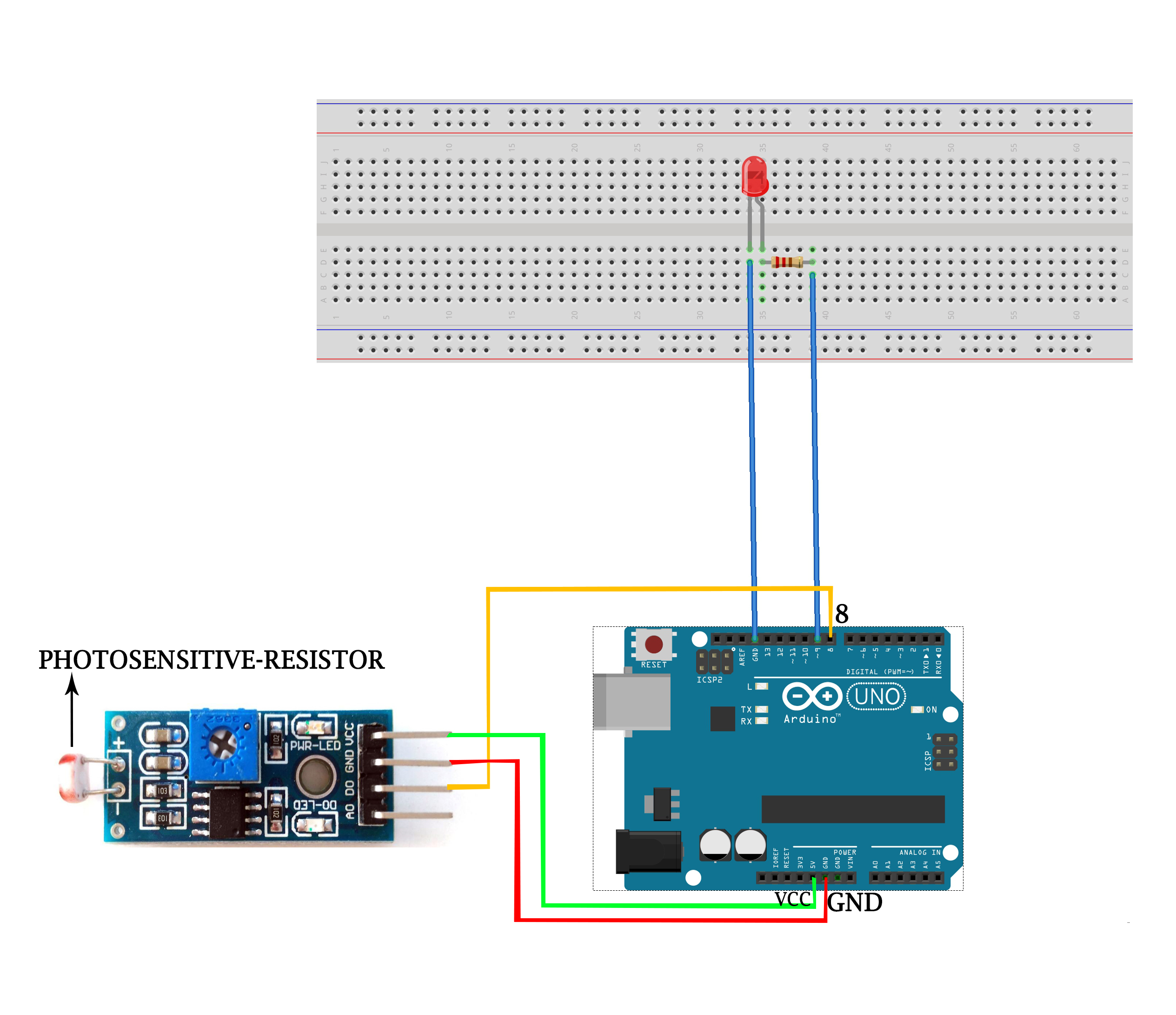
Once the components are collected, do the circuit connections as given below.
In the input part of the circuit, LDR sensor module is associated with both analog output pin and digital output pin labelled as AO and DO respectively on the board. Also it has VCC and GND on it. Connect VCC to 5V and GND to GND pins in Arduino board respectively. The DO pin should be taken as input to the Arduino through any of the digital I/O pins (Here we consider pin 8). Similarly, if you want to know the analog value of light intensity, AO should take as the input to Arduino through any of the analog input pin (here, we aren't considering this part).
Considering the output part of circuit, plug the short leg of LED into the GND (ground) header. Also connect the positive leg to digital pin '9' as per the code we use now. You can use any of the other digital pins, and change the '9' in your code to match. Don't forget to add a resistor in between positive leg of LED and digital output pin of Arduino, to prevent the burning of LED due to high voltage. Remember, a resistor can connect in either way around. Use a bread board and a pair of jumper wires to make all the above mentioned connection.
If you are designing this for home automation or street light control like applications, you directly use a AC bulb and relay instead of LED and resistor respectively.
To see the digital output value of LDR sensor, you open use serial monitor as given below.
Tools->Serial Monitor


_ztBMuBhMHo.jpg?auto=compress%2Cformat&w=48&h=48&fit=fill&bg=ffffff)


Comments
Please log in or sign up to comment.