


Hardware components | ||||||
_ztBMuBhMHo.jpg?auto=compress%2Cformat&w=48&h=48&fit=fill&bg=ffffff) |
| × | 1 | |||
 |
| × | 1 | |||
 |
| × | 3 | |||
 |
| × | 4 | |||
 |
| × | 1 | |||
Software apps and online services | ||||||
 |
| |||||
Hand tools and fabrication machines | ||||||
| ||||||
In this project I am going to discuss about the basics of RGB LED light.
RGB LEDRGB LED is a combination of 3 different LEDs and they are Red, Green and Blue. We can use it in different purposes. Some common usages are designing our home, event stage design, LED matrix display etc. An image of RGB led has shown below:
As we mentioned above that the RGB led has three types of led in itself. These LEDs are sharing common anode or common cathode. On this basis we can divide RGB LED into two types, one is Common Anode RGB LED and another one is Common Cathode RGB LED.
Common Anode RGB
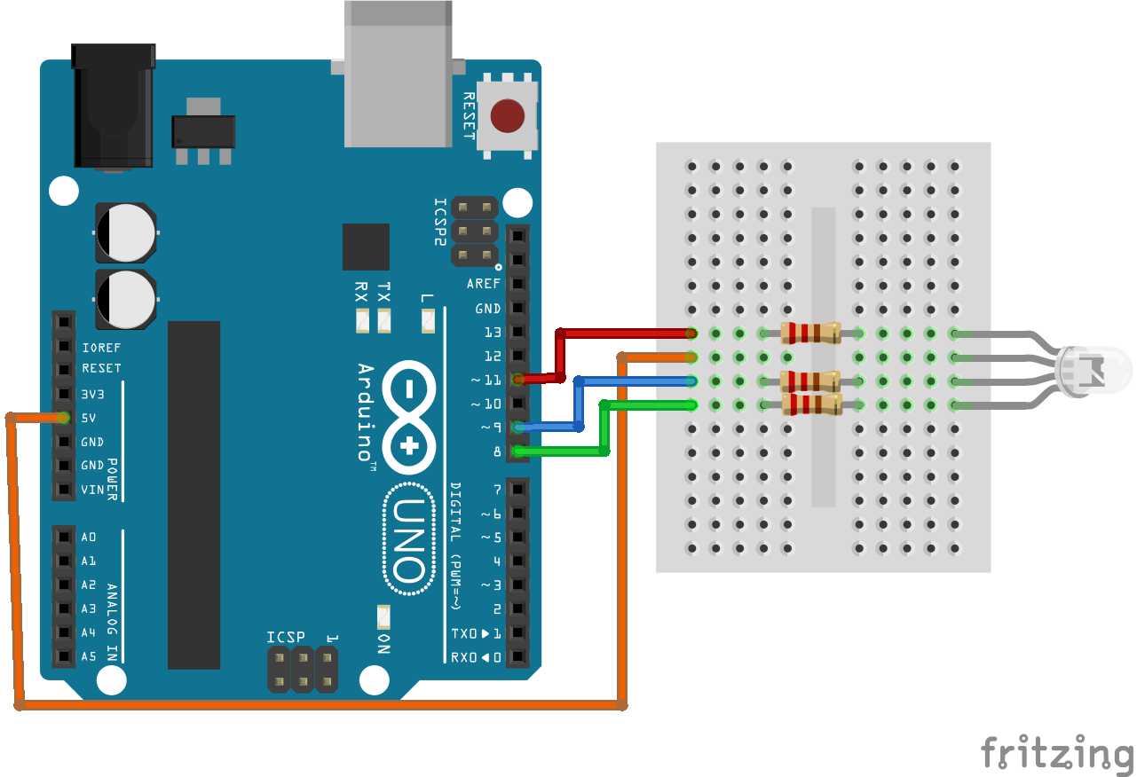
All three led's anode will be short with each other internally. Then this common point will be attached with the RGB anode. We just need to add this common point to the positive terminal of the power source. On the other hand other three terminal will need to attach to the digital pin of the Arduino.
Common Cathode RGB
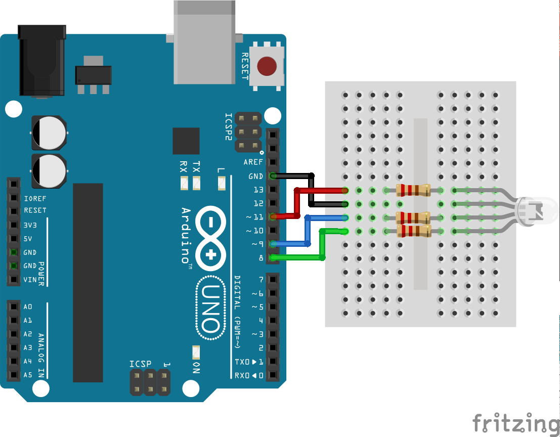
In this type of RGB all three internal led's cathode will be short with each other. Then the RGB LED's cathode will be attached to the common cathode point of the LED. Here, we just need to add the GND terminal of Arduino to the common point that is basically the cathode point of the RGB. Remaining three pins will be connected with the digital pins of the Arduino.
Two types of RGB LED image has shown below:
Arduino ------------------------ RGB LED
Digital Pin - 8 ----------------- GREEN LED
Digital Pin - 9 ----------------- BLUE LED
Digital Pin - 11 ----------------- RED LED
+5V ------------ Common point (Anode Pin)
Demonstration VideoNoteIn demonstration video we have used Common Anode RGB LED and in Tinkercad project we have used Common Cathode RGB LED.Links
Github Repository Link: https://github.com/KAST-Tech/arduino-basics-projects/tree/main/Project-%234
Tinkercad Project Link: https://www.tinkercad.com/things/abAcGTAehVM


Comments
Please log in or sign up to comment.