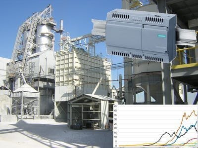
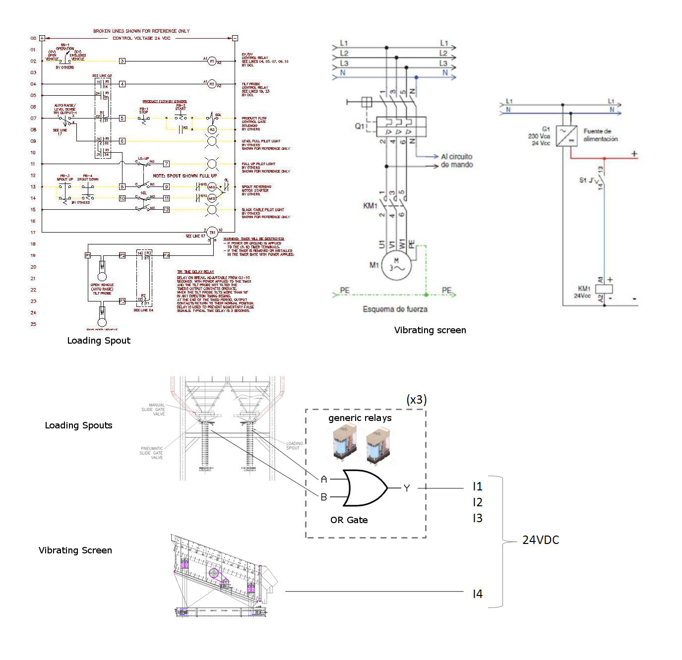
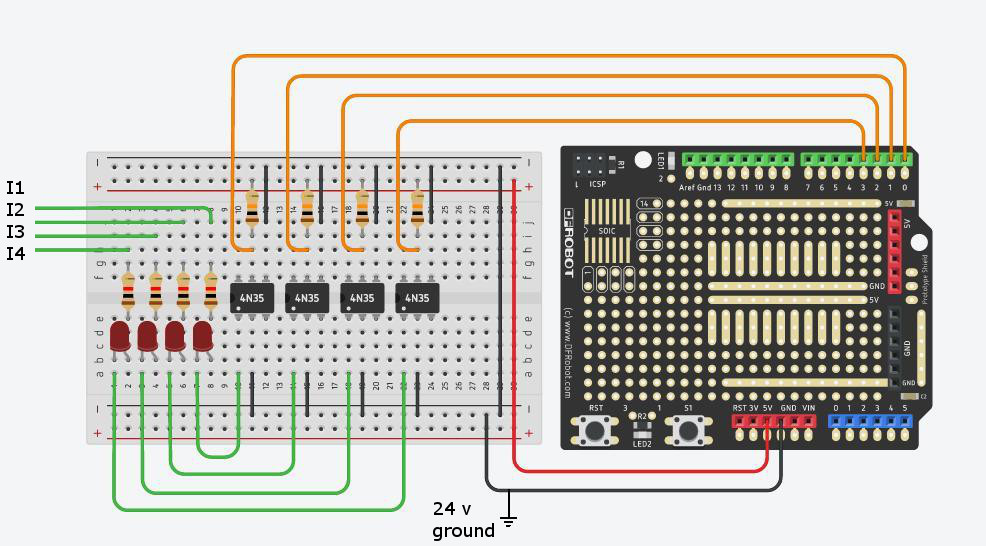
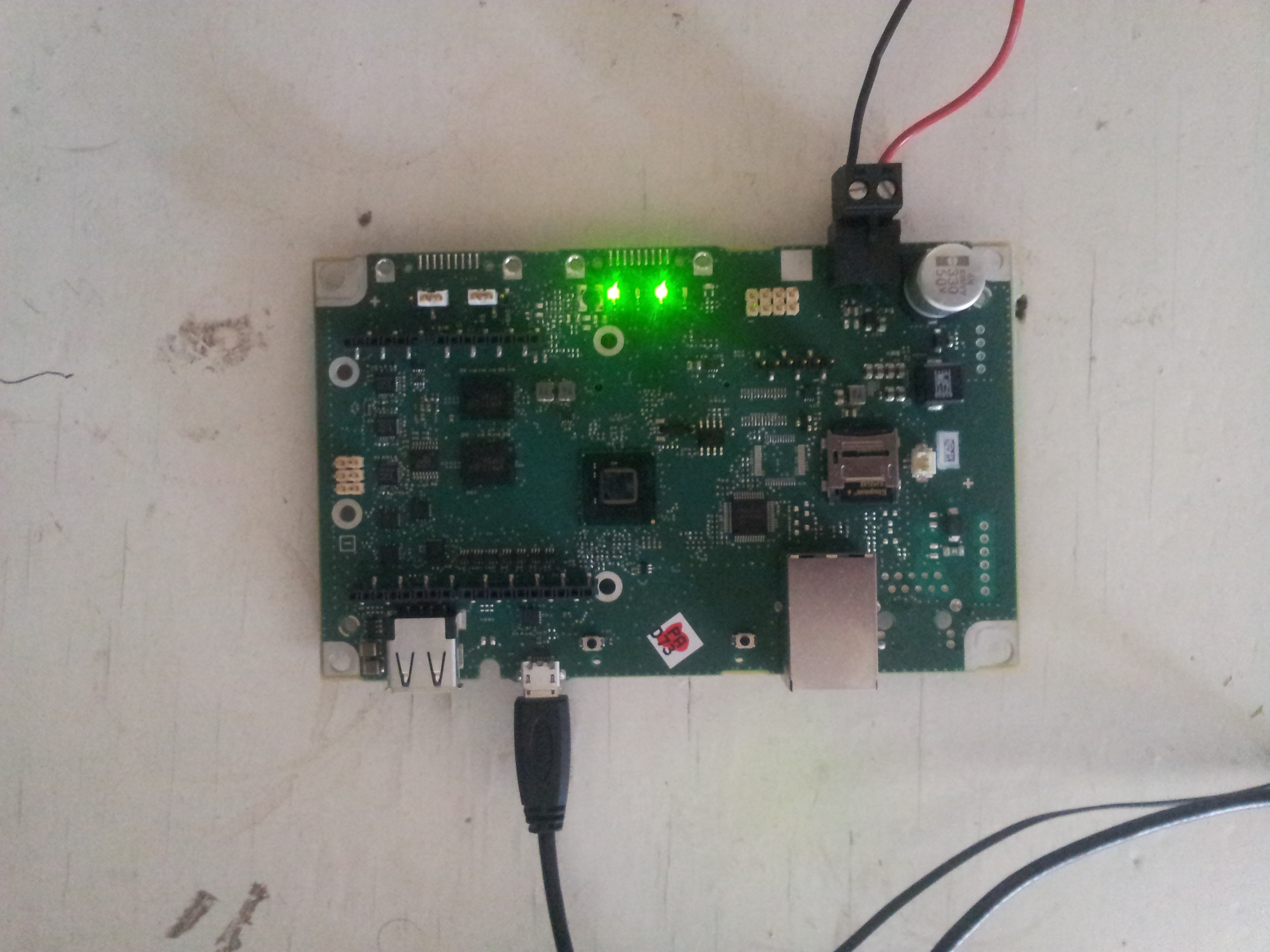
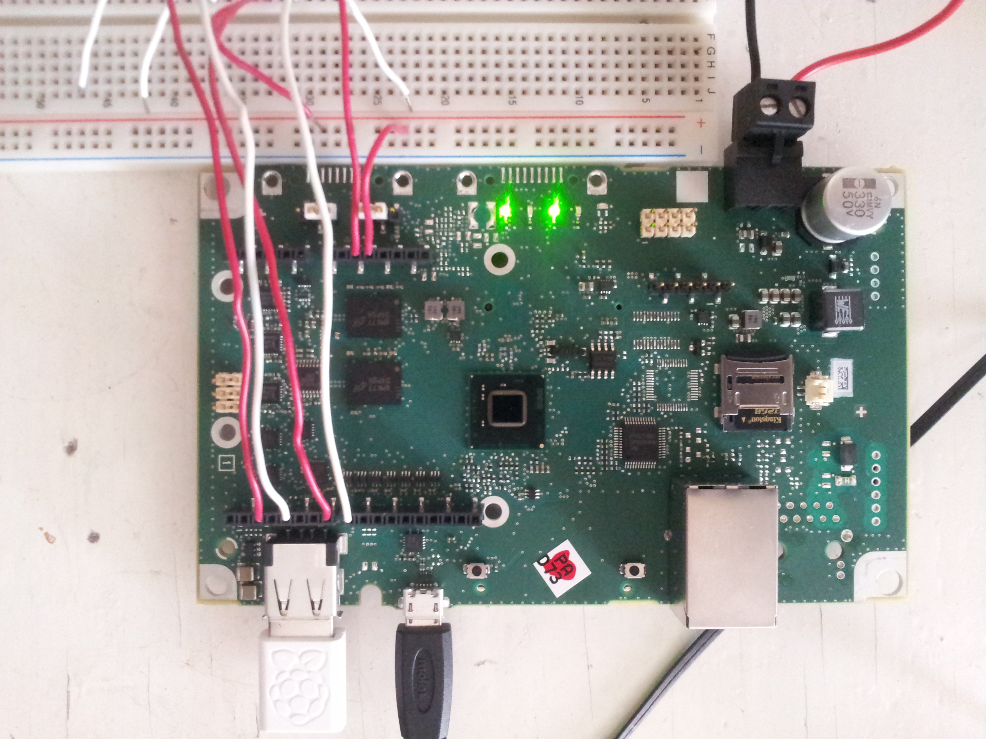
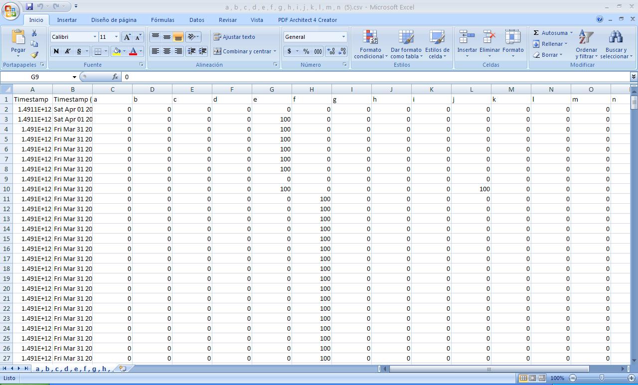
This idea is to use a Simatic IOT2020 as a console that allows us to collect the status of the operation of a gravel silos for a period of one year, this system has a dust collection system. The objective is to obtain the state (on/off) in which its components work, to characterize the behavior of the system and to review potential energy saving opportunities.
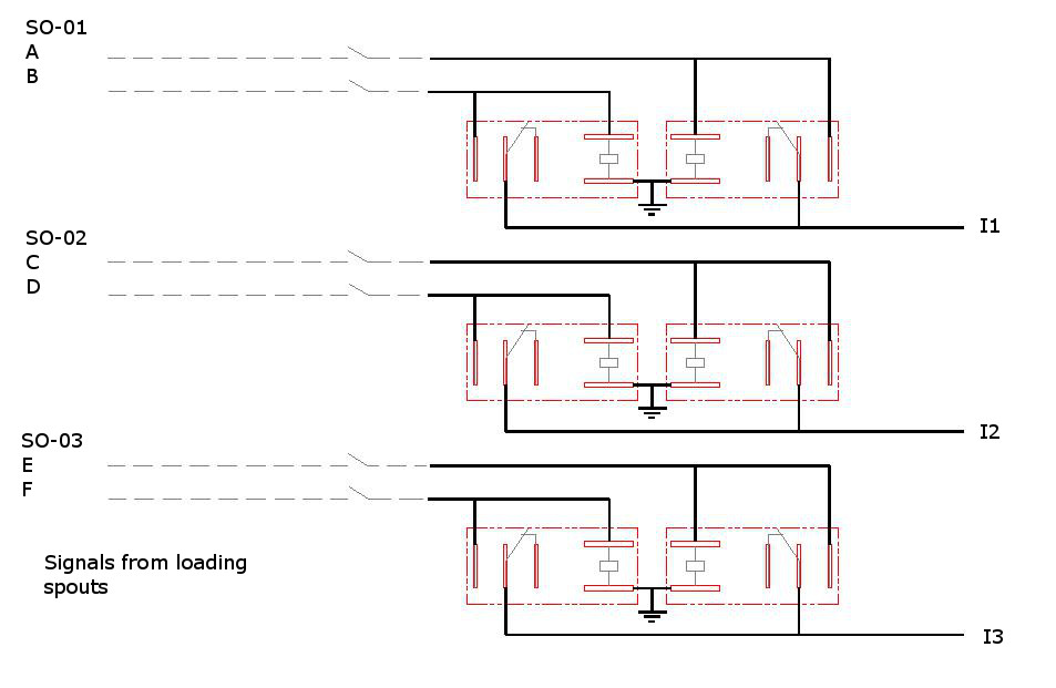
System DescriptionThis system consists of three pairs of hoppers which are fed by means of a vibrating screen. The discharge to truck is through loading spouts when the discharge valves of the hoppers are operated, to avoid contamination by dust of the operational area. There is a dust collection system; this system performs the suction of dust on the points of capture: loading spouts, vibrating screen and the top of the silos, this suction must be made every time you work on filling some truck with gravel or when the silos are filled.
The original system was designed considering that it would be a single main line from the vibrating screen to the dust collector, and all other components would join this main line. This design requires a fan size 071 which will have a fan shaft power of 16.79 KW and an efficiency of 83.3%.
This mode of operation implies that the system will always work to the maximum capacity, regardless of whether the suction is being carried out from a single point of capture, or from all the capture points at the same time. This is because the same transport speed must always be maintained in the suction lines to prevent settling.
SolutionThe solution to this dilemma is to connect each capture point with separate lines to the dust collector, this would allow us to vary the flow of the system according to the operating requirements, isolating the rest of the lines without having to worry about low transport speeds.
The following figure shows the fan options we require for each mode of operation.
The simplest option is to leave a fan model 040 and a fan model 056 connected in parallel, we can work with model 040 for cases 2, 3, 4 and 5, we can work with model 056 for cases 6 and 7 and for Cases 1, 8 and 9 will operate both fans at the same time. To achieve this it is necessary to consider Vfds for both fans
The following figure shows the power consumption of both fans for the modes 1, 8 y 9.
As we can see there are opportunities for energy savings in the modes of operation 2,3,4,5,6 and 7 the convenience of the investment depends on the cost of the modifications and the material required: two fans with Vfds, the instrumentation and valves with their actuators. Another important consideration in energy saving projects is the return of investment (ROI), the cost of electric energy, the electric demand, and the annual electric consumption. To obtain the annual electrical consumption we require the annual operating time of each operation mode, this is where our industrial console of electric consumption comes into play.
An extra advantage of using the Siemens IoT2020 platform is that in case the project has an economical feasibility, then the same IoT 2020 platform can be used for the control of fans and line isolation (and regulation) valves. With this in mind the cost of the investment could be reduced since we saved the cost of an industrial PLC.
The use of this information does not stop, only in this study of energy saving. This data can also be used in the maintenance of the equipment, in the sales area to establish market strategies, etc.






Comments
Please log in or sign up to comment.