


Program for creating a firmware templateThe simplest programming of the STM32F103C8 microcontroller
Purpose of creating this program::
- make microcontroller programming simple
- remove restrictions on the use of MK resources inherent in Arduino
- easy integration of your own program code
- Hardware
- Software
- Of course, first of all the controller itself. "Blue Pill":
- USB-UART adapter:
- Micro-USB cable:
- a set of wires for connecting components to each other:
- For faster, in comparison with UART, downloading the "firmware" and debugging programs, it is recommended to use the ST-Link V2 programmer, for example this:
All used parts / components can be purchased on aliexpress.com.
Software- STM32 Flash loader demonstrator (FLASHER-STM32)
- STM32 Virtual COM Port Driver (STSW-STM32102)
- STM32 ST-LINK utility (STSW-LINK004)
- www.embitz.org IDE
- MIOC - program - configurator. Creating a firmware template
- terraterm - terminal emulator
A module is a combination of hardware and software. The hardware is the STM32F103C8T6 “Blue Pill”, the software is the “firmware template” created using the MIOCprogram. This program is OpenSource.
Microcontroller portsThe microcontroller haspins or legs. Some of them are power of microcontroller, some have aspecial purpose (for example, Reset), some are general-purpose input/ output interface (GPIO).
Ports are grouped as (A;B; C...). Each group contains up to 16 ports, numbered from 0 to 15.As a result, the port numbering looks like PA0, PA1, …
Ports are used forcommunication between the components of the module, for example, amicroprocessor and various peripheral devices. Ports can act asinput, output, and bidirectional.
The “Blue Pill” board have a marked withports.
GPIO - General Purpose I / O InterfaceThe main types of ports the IO module are presentedin the table:
GPIOModeAIN
analog input
GPIOModeIN_FLOATING
entrance without pulling ( Float )
GPIOModeIPD
pull-down entrance ( Pull-down )
GPIOModeIPU
pull-up entrance ( Pull-up )
GPIOModeOut_OD
open drain ouput ( Open Drain )
GPIOModeOut_PP
two-state output ( Push-Pull )
GPIOModeAF_OD
open drain output for Alternate Function. Used when pins are controlled by peripherals that can be used on this pin. For example, USART, I2C, and the like.
GPIOModeAF_PP
same as GPIO_ModeAF_OD, but with two states
As sensors, actuators we will use various devicesfrom Arduino.
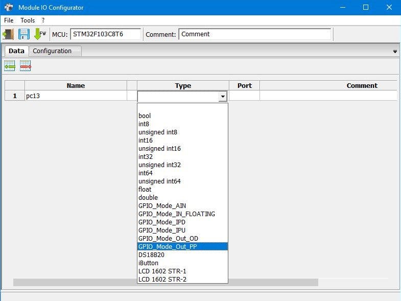
MIOC (Module Input-Output Configurator) ProgramUsing this program, wecreate / configure the firmware template (project for Embitz; Keil)of the IO module. The program does not require of installation.Download, run. Using this program, we create global variables that wewill use in our firmware. Variables can be associated with ports.
First run window:<ont>
Create a project:<ont>
Blink the LED, which is onthe "blue pill". This LED is connected to the PC13 port.
Add row to variable table<ont>
Generate BSP code (F8 button)<ont>
Further, each time, after a project change, the generation of BSP is mandatory!
Open the created projectin the development environment of EmBitz or Keil. EmBitz is still atemporary solution, it seems the author abandoned this project.Apparently in the future, the project will use Code::Blocks.
In the main.c file, write the following:<ont>
(To increase the size of the image, open it in a newtab)
In EmBitz, press F2, after the information window appears, press F7, compilation will be performed.Pressing F2 again will hide the information bookmarks.<ont>
Download to the microcontroller, look how it works.
ButtonAdd a button, for example this:
wiring diagram
Add a variable to the table:<ont>
To generate BSP.
Change the program to the following:<ont>
We create a new BSP (F8), compile it, load it intothe microcontroller.
We press the button - the LED lights up, release - itgoes out.
Instead of an LED on another port, you can connect arelay, like this:
You need to determine what will be the console.
The options are:
- USB-UART adapter
- virtual COM port (Micro-USB cable)
If both UART1 and USB asConsole are selected in the configuration, and USB VCP is notselected, the console will be assigned to nowhere. Those. there willbe no swearing at the print_str function (or the print macro), butthere will be no output either. The same behavior will be if you donot select any interface, or select USB VCP, but do not select eitherUART1 or USB as Console.
Console Configuration:<pan>
Connect TettaTerm to theCOM port (console). If we download the firmware via UART1, then donot forget to disconnect / connect the COM port. TerraTerm hotkeysAlt + I; Alt + N This is not required for the boot option viaST-Link.
Edit the program:<ont>
The console will now display the status of the button.<ont>
Connect the DS18B20 temperature sensor to the "Blue Pill":<ont>
Put the variable in the configuration:<ont>
Change the program to the following:<ont>
Create a new configuration, compile, load it into themicrocontroller.
The console will display the temperature measured by the sensor.<ont>
As an example of working with the ADC, you can use the potentiometer<ont>
or soil moisture sensor<ont>
Let us dwell on the last one:
Configure the port:<ont>
Editing the program:<ont>
Compile, load.
In the console we observe:<ont>
adc - current ADC reading, max and min - recorded minimum and maximum sensor readings, completely dry (0%) and very wet (100%).
Very wet (100%) - put thesensor in a glass of water. Very dry (0%) - lies in the open air.
In fact, we calibrated the humidity sensor from 0 to 100%. The maximum and minimum values are placed in the program text.<ont>
The result of the work. Sensor in a flower pot:<ont>
This project is a solution template for wateringplants.

Comments
Please log in or sign up to comment.