


Hardware components | ||||||
| × | 1 | ||||
 |
| × | 1 | |||
 |
| × | 1 | |||
| × | 1 | ||||
| × | 1 | ||||
| × | 1 | ||||
Software apps and online services | ||||||
 |
| |||||
 |
| |||||
| ||||||
 |
| |||||
| ||||||
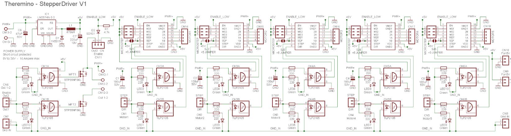
Theremino StepperDriver
This module allows you to mount up to five drivers for stepper motors and has two exits with MOSFETs to drive motors, relay or hot wire to the polystyrene and adjust them in PWM.
You can install various types of drivers (Drv8825, DRV8824, A4988 and other similar). Drivers are easily replaceable so if something breaks you should not replace the entire plate but only one driver. Among other things the drivers only cost a few euros so you can always keep a spare and not risk never to stay with the machine at a standstill.
The special feature that distinguishes this tab from the usual tabs (type Ramps or CncShield) is to be totally photo-coupled. You can then maintain a complete galvanic isolation between the control logic and power electronics of the machine. This avoids ground loops and all the risks associated with them.
Attention to the bridge marked “Out2″/”On”. Place the jumper on “On” to enable the drivers otherwise will not work. If placed on “Out2” then the second Mosfet no longer usable because its photo-Coupler is designed to enable the five drivers.
Inputs specifications
- Photo-coupler inputs are driven with at least 3 volts.
- You must keep separate the masses of the inputs from the masses of power.
Power features
- The main power supply can be from 8 to 36 volts. Should not exceed 32 volts to get yourself some’ of margin.
- The electricity needed to power the Stepper is lower than the setting on the Trimmer. The total may reach a maximum of a few amperes with five drivers, all regulated the maximum current and voltage of only 8 volts. As the voltage decreases current halls. Normally just a two amps.
- If the main power supply must supply the loads connected to the Mosfet then you must dimension taking account of these currents, up to about 16 Ampere. Best not to go beyond.
- A connector (on the left) reports the positive supply voltage and connections to two Mosfets. If you don't want to use the same supply voltage can be left disconnected the power pole of this connector and use an external power supply.
- The maximum voltage tolerated by the Mosfet is 60 volts but it's better not to exceed 50.
- The current maximum bearable by the Mosfet is 20 amperes (without heatsink) and up to 30 or 40 with a good heat sink. Sure that the metal part is not isolated. Then you can probably be able to dissipate just left mosfet, coricandolo. These are maximum current, If it exceeds 10 amps at Mosfet is well evaluated case-by-case basis and do many tests.
- You can control the PWM Mosfet up to quite high frequencies, even hundreds of KHz. However, we recommend that you use no more than 20 KHz in order not to increase their dissipation.
- Mosfet switching times are less than 100 NS.
- The delay produced by the photo-Coupler is 300 NS (version 1) or of 800 NS (version two).
Characteristics of 5 Volt fan
- The Switching regulator on board creates a 5 Volts for logic and for the fans.
- Two connectors with 5 Volts for two small fans to be placed on a plastic mount done at “U” sliding the air along all drivers. With the fans and heatsinks can use drivers up to the maximum specified current in their characteristics. For three drivers mounting one fan, for five if you mount two.
- The maximum current drawn from the 5 Volt is about 400 but in total.
Versions 1 and 2
There are two identical versions as features and also as size. The only difference is the type of photo-couplers that are mounted and the associated components.
The version 1 use the photo-coupler TLP2105. These photo-couplers are hard to come by and cost enough, but they are “no reversing” and then the circuit is simpler.
The version 2 USA photos-couplers HCPL-0531. These photo-couplers are easy to come by and cost less, but invert the signal and therefore require an additional transistor.
Downloads
Complete projects in Eagle format, 3D images, diagrams and component data sheets:
http://www.theremino.com/wp-content/uploads/files/Adapter_StepperDriver_V1.zip
http://www.theremino.com/wp-content/uploads/files/Adapter_StepperDriver_V2.zip
Multiplier of inputs and outputs
The Theremino Multiplexer is a switch to eight locations, that accepts analog and digital signals of any voltage from 0 to 5 Volts. The signals can travel in both directions, from a Master output to eight actuators, or eight sensors to a single entrance to the Master.
Some examples
– Connect up to eight Magnetometers to a single FastCounter.
– Connect up to eight sensors to a single entrance Adc16.
– Connect up to eight Relays in a single output DigOut.
Features The closed contact is like a very low resistor (less than 100 ohm resistor). The open contact is like a resistor high (about 50 Mega ohm). The total power consumption is a few micro Amperes. The leakage current is less than 100 Nano Amps. The switching time is less than 20 NS, transit time is 12 NS and parasitic capacities are a few pico Farad.
Have characteristics similar to those of a mechanical switch, so you can use it up to frequencies of 100 MHz and beyond.
Peculiarity of this adapter
Before choosing this adapter for your applications, make sure that the sensors and actuators will run only one at a time. In addition to switch from one channel to another it will take some time (about 50 Ms to give time to the HAL to execute with certainty the switching and also some time, variable depending on the sensors, to stabilize the signal).
It is used to multiply the outlets (Digout, Servos or Pwm), make sure that the outputs are not enabled you are flying. Then, in case of actuator with high impedance input, to avoid accidental activations, you will have to add 10 k resistors to ground for each actuator. The resistors were not added to the basic design, because it would have prevented to read some sensors.
Use a 74HC4851 instead of the 74HC4051
The classic 4051, that has existed for decades, It works fine but, If possible, It would be better to use a 4851, which has a higher tolerance to disturbance on channels not connected (in the project download there are PDFs of both integrated). Both the ICS cost around half a Euro and the 4851 It is easily found by both Mouser that Farnell, so the only reason to use the 4051 is thus already someone in drawers. Who should buy them choose the 4851.
Project download
The design of the PCB is completely in step 2.54 mm. Build it on a Breadboard thousand holes is really easy. You put the components from above, Turning the power strip and using small single wires (for example, cut by the resistors), to make the few necessary links.
Download the complete project Eagle PCB, Gcode for the cutter and 3D images: Theremino_Multiplexer
Variable voltage PWM adapters
To pilot the following adapters, It starts with a Pin configured as Pwm8, Pwm16 or FastPwm.
The types Pwm8 and Pwm16 have a fixed switching frequency 250 Hz and an accuracy of about one part in 5000,
The type FastPwm could be regulated by 1 KHz to 20 KHz. With 1 KHz resolution is one part in 65000. Rising frequency decreases the resolution but also decreases the residual noise of switching cycles. The best compromise between resolution and noise you get with a frequency of 15 KHz.
From Pwm to 3.3 Volts
With this simple circuit you get an output voltage ranging from 0 to 3.3 Volts, a DC voltage stable enough (less than 100 MV residual noise), and a response time of a fraction of a second.
From FastPwm to 3.3 Volts
Generating the signal with a Pin configured as FastPwm and adjusted for a frequency of 15 kHz, you get a lower noise. Because it starts from a higher frequency filter capacitor can be reduced to 1 UF and get a quicker response.
From Pwm or FastPwm to 0..5 Volts
This version has the same features of the previous, but the output voltage varies from 0 to 5 Volts (instead of 0 to 3.3 Volts).
To have a quicker response and a lower residual noise, You can use a FastPwm type output (with frequency 15 KHz) and decrease C1 to 1 uF.
The design of the PCB is completely in step 2.54 mm. Build it on a thousand holes (from 9 x 7 holes) It's really easy. You put the components from above, turns around and use the same resistor wires, to make the few necessary links.
Eagle project downloads, Gcode for the cutter, 3D images and simulations: Adapter_PwmTo05
From Pwm_16 to 0..10 Volts
Having a voltage of 12 Volts, and with a slight variation of the previous circuit, You can generate an output range from 0 to 10 volts.
The current absorbed by the 12 Volt is less than 100 mA, so whatever small power supply can fit.
By changing the value of the resistor from 39 ohm you could also use a power supply with a voltage other than 12 Volts, According to the table below:
- Power supply unit 10 Volts, resistor = 0 ohm resistor
- Power supply unit 12 Volts, resistor = 39 ohm resistor
- Power supply unit 15 Volts, resistor = 110 ohm resistor
- Power supply unit 18 Volts, resistor = 180 ohm resistor
- Power supply unit 24 Volts, resistor = 300 ohm resistor
From Fast_Pwm to 0..10 Volts
In this circuit was added a resistor from 100 ohm and diminished the output capacitor to expedite your requests and to be able to fly with a Fast_Pwm output adjusted 15 KHz.
This way you get an output noise almost ten times less and a speed of answer ten times better.
The current absorbed by the 12 Volt is less than 100 mA, so whatever small power supply can fit.
By changing the value of the resistor from 39 ohm you could also use a power supply with a voltage other than 12 Volts, According to the table below:
- Power supply unit 10 Volts, resistor = 0 ohm resistor
- Power supply unit 12 Volts, resistor = 39 ohm resistor
- Power supply unit 15 Volts, resistor = 110 ohm resistor
- Power supply unit 18 Volts, resistor = 180 ohm resistor
- Power supply unit 24 Volts, resistor = 300 ohm resistor
From PWM to 5 Volts, with low noise and fast response
For those who want maximum performance, Here is a more elaborate version. Designed to control Vintage synths, has a residual noise of a few millivolts and speed of response around one-hundredth of a second.
The complete project of this version is the page dedicated to music. Click on this link: PWM to ControlVoltage
Adapters for use with photo-couplers
Some devices, for example, some drivers for stepper motors, they paired photos inputs. Normally these photo couplers work well with Pin configured as Stepper or piloting them as DigOut. But in some cases, Depending on the internal circuit of the drivers, paired photos inputs can not settle, voltage and current that we send. In these cases may malfunction or not function right.
In all cases you should check, in device characteristics, It can work with inputs of 3.3 Volts and with 5 MA or less. In the case that 3.3 Volts are not enough, or if you have doubts about working at the limit of voltage or current required, You can insert this adapter.
Click on the image for a larger view.
Note that the output of this adapter is not related to mass. Then you should connect only to devices blocks (How are the pictures-couplers). You could also fly small relays or motors (always isolated from all) but in this case you should add a protection diode, as in this example.
Stabilized regulator 5 Volts
Some sensors require a very stable voltage supply. Sometimes they are referred to as “Ratiometric”, that is, with output voltage which is a fraction (ratio), the supply voltage. Other sensors, simply, are not stabilized internally and generate a signal less noisy, If feeding with stabilized voltage.
The 5 Volts coming from USB or external power supplies is never accurate. In some cases also varies the 10% (from 4.5 Volts up to 5.5 Volts). Also some PCs and notebooks provide a 5 Volt very noisy, with rapid changes, also of several hundred millivolts.
In some cases you may use the stabilized voltage at 3.3 Volts, that is available on the ICSP connector of the Master modules, Servant and CapSensor. Or you could use remote controllers 3.3 Volts or 4.2 Volt on this page. But some sensors want to own the 5 Volts.
If the sensors are many, It might be useful to insert this control along the serial line that goes from the Master to the slaves. So you would get to stabilize in one fell swoop all sensors and modules that are located downstream of the regulator. Stabilize sensors connected to the Pin of the Master is a little’ harder (possibly read Handout Master to locate the point where you could stop the 5 Volts going to pins).
This adaptor generates the 5 Volts from 5 Volt unstable, from the USB, The first part of the circuit is a step-up, Flyback, It generates about 7 Volts. The second part is a linear regulator that generates a 5 Ultra Volt stable, precise and quiet.
One feature that many will appreciate is to only use common components. The reel can be extracted from fluorescent lamps and the resistors can be also from 1/4 Watts (Messi standing). And, with a little’ of attention, You can also build on a thousand-base holes.
The maximum output current is approximately 100 mA, then you can use it to stabilize many sensors simultaneously. Not all sensors need a 5 Ultra Volt stable, but sometimes you may want to feed all through a single regulator. In these cases, you must make the partial currents amounts to verify that you are in 100 but available.
The following tables list the consumption of the main sensors and modules of the system Theremino.
Modules and sensors that need 5 Volts stabilized
HIH4000 (moisture): 0.5 mA
MPXA6115 (pressure): from 6 to 10 mA
FGM1 and FGM3 sensors (jerks): 12 mA
Magnetic sensors (A1301 and A1302): 11 mA
Accelerometer triple LIS344 (directly from 5 Volts): 0.7 mA
Modules and sensors that take minimal benefits from the 5 Volts stabilized
Lm35 (temperature): 0.1 mA
AD592 (temperature from -25 to +105 degrees): 0.4 mA
Ultraviolet sensor (UVM30): 0.1 mA
Pmt adapter (photomultiplier tubes for Gamma Rays): from 10 to 30 mA
Modules and sensors that must be fed to 3.3 Volts
Ultraviolet sensor (ML8511): 0.3 mA
Modules and sensors that do not require 5 Volts stabilized
Sensors for Lightning and electromagnetic fields: from 2.5 to 4 mA
Piezoelectric sensors for floppy disks: 0.01 mA
Ionic room preamp (version 5): 8mA
Feeder 475 volts per ion Chambers: from 10 to 20 mA
Accelerometer triple LIS344 (connected to the triple preamp.): 0.7 mA
Triple pre-amplifier for accelerometers: 2 mA
Pre-amplifier “GeoPreamp” for the Geophones: 0.3 mA
Sensors for dust spectrometry: from 10 to 20 mA
Operational modules LMC6482: about 1 mA
Madulo slave “Servant”: 10 mA
Slave module “Capsensor”: 12 mA
Form “Master”: 12 mA
Download the complete project Eagle PCB, Gcode for the cutter and 3D images: Adapter_Stab5V_V 1.2
Stabilized regulator 5 Volt small version
This adapter is much smaller than the previous. The output voltage is very accurate but slightly’ noisier (do not worry… We are always in the area of hundreds of micro Volts).
It's called Geomagnetic because it was developed for sensors FGM1 and FGM3, but it is also useful for other sensors, for example, atmospheric pressure sensors MPXH6115A and those of moisture HIH4000.
The supply voltage can range from 3.5 to 5.5 Volts and the output is 5 Volt precise. The addition of a pre-remote controller 3.3 Volt adds further stability to changes in input voltage. If the regulator is not necessary, just delete it, combining C1 with C2 with a wire (in this case the input voltage may vary from 2 to 5.5 Volts). The maximum output current is around 150 mA, then one of these adaptors might feed many sensors. For example a dozen FGM1 or FGM3, they consume 12 but the one.
In addition to stabilize the voltage This adapter lowers the sensor signal (usually from zero to 5 Volts), towards the voltage values suitable to the inputs of the system theremino (from zero to 3.3 Volts). If this adaptation does not serve you delete R2.
Download the complete project with Eagle PCB, Gcode for the cutter and 3D images: GeomagneticAdapterV2
Stabilized regulator 3.3 Volts
Some sensors, the potentiometers e.g., work best if they are feeding with a stabilized voltage of 3.3 Volts, other sensors, as the magnetic sensors and accelerometers, require a voltage from 3.3 Volt stabilised.
The tension of 3.3 Volt is available on all modules of the system Theremino on the ICSP connector. To get the lowest possible noise, or for wiring requirements, the tension of 5 Volts can be lowered to 3.3 Volts and stabilized with an adapter.
Here's a simple adapter, inexpensive and tiny which can be used with the standard male-female. A version of this adapter, without connectors, can be welded along the wire and covered with a heat-shrink sheath tube getting a small, stout wiring.
Generally manufacturers recommend placing the condenser (and then all the adapter) near the sensor so it is good to keep the piece of wire between the adapter and sensor not longer than a few centimetres. For some sensors recommends a tallish capacitor (10 uF) in this case you could increase the C2 (always use ceramic capacitors SMD electrolytic capacitors that cost much less than the, have a low impedance and are very small – 0805 or 0603) In all our trials, even with the most demanding sensors, We have verified that the C2 from 1 UF is sufficient, because the voltage regulator stabilizing also helped by good at medium to high frequencies. The C1 you can definitely minimize 100 NF and probably reduced in future releases to decrease the total capacity on the USB line that is given for a maximum of 4.7 uF.
Download the complete project Eagle PCB, Gcode for the cutter and 3D images: Adapter_Stab
Stabilized regulator 4.2 Volts
Some sensors, for example the HIH4000 and HIH4030, can be fed with 4.2 Volts stabilized and provide a release from excursion 0 to 3.3 Volts. In these cases you avoid having to add the battery isolator (from 5 to 3,3) or the limiting resistor (usually from 33k).
You cannot use the classic controller (for example the LM317) because they have a minimum voltage drop of almost 2 Volts. You have to use type LDO regulators. Currently (2014) the best LDO are those of the series AP2125.
The regulator 4.2 AP2125N-TRG1, produces a voltage of 4.2 Volt very stable and little noisy. The pinout is the same as the MCP1700 voltage regulator, You can use the same patterns from the previous section.
The 4.2 AP2125N-TRG1 It's very cheap:
Code Mouser: 621-4.2 AP2125N-TRG1
Package: SOT-23-3
MarkingID: Gj3
Price (approx): 0.3 Euro
There is also the version from 3.3 Volts which can replace the MCP1700 voltage regulator. Pin-compatible but cost less and best features of stabilization and noise.
Code Mouser: AP2125N-3.3 TRG1
Package: SOT-23-3
MarkingID: GJ7
Price (approx): 0.3 Euro
Here you download the data sheet of the whole series of AP2125N, from 1.8 Volts to 4.2 Volts
http://www.mouser.com/ds/2/115/AP2125-271646.pdf
Download the complete project Eagle PCB, Gcode for the cutter and 3D images:
Adapter_Stab
Power adapter
When you exceed the maximum current of the USB port (500 mA) transmission errors may occur, detachments of the USB line and error messages from the PC.
Although the average consumption is low enough may cause you to exceed the maximum current during starting of engines or other brief occasions. Also some PCs are very sensitive even to very short consumption tips and stop immediately feeding.
You can try to increase the maximum current drawing current from two USB ports with a cable but usually the only real solution is to stop the supply line in the most appropriate and insert an external power supply with this adapter.
The external power supply will usually be from 5 Volt 2A and up to 5 Amps in some cases. If you require a higher current (up to 10 or 20 Ampere) standard cables can no longer use but use good quality silicone strips trifilar windings paid directly or screwed to the version of the adapter with screw connectors on the following page.
These adapters can be built easily, even without printed circuit board, using a small swatch of stripboard.
Power adapter version with screw connectors
For currents greater than 2 Amps should I use this adapter with screw connectors and cables with large diameter as specified in section “Connection cables”
Up to 5 Amps cables from 20 AWG (0.52 mmq)
Up to 10 Amps cables from 16 AWG (1.3 mmq)
These adapters are built easily, even without printed circuit board, using a small swatch of stripboard.
Current limiter
These current limiter followed by a large-capacity electrolytic can solve even the most difficult situations without adding an external power supply. The limitation is very accurate, much better than that of PTC normally used in USB and in case of short circuits the output “turns off”, and you “on again” automatically as soon as you remove the short (operation at “foldback”).
The limiter must be interposed between the +5 Volts coming from the USB and power track that goes to pins.
Changing the values of the resistors you can choose the maximum current.
The limiter must be interposed between the +5 Volts coming from the USB and power track that goes to pins, You can do both on the Master and Slaves by cutting the track that bears + 5 volt to pins and welding three wires.
Attention: You just have to limit the power of In-Out Pin, not the processor power. Do not place surge down the serial line.
And’ easy to build this version (not SMD) even without printed circuit board, using a small swatch of stripboard. All components are in step 2.54 mm (hole spacing), then with the same resistor terminals are the connections on the back and within minutes you end up.
Eagle project downloads, 3D images and simulations LTSpice, version limiter ThruHole: Adapter_Limiter
Current limiter SMD version
These current limiter followed by a large-capacity electrolytic can solve even the most difficult situations without adding an external power supply. The limitation is very accurate, much better than that of PTC normally used in USB and in case of short circuits the output “turns off”, and you “on again” automatically as soon as you remove the short (operation at “foldback”)
Changing the values of the resistors you can choose the maximum current.
The limiter must be interposed between the +5 Volts coming from the USB and power track that goes to pins, You can do both on the Master and Slaves by cutting the track that bears + 5 volt to pins and welding three wires.
Attention: You just have to limit the power of In-Out Pin, not the processor power. Do not place surge down the serial line.
Eagle project downloads, 3D images and simulations LTSpice of limiter in SMD version: Adapter_LimiterSMD
Adapter for CNC machines
Attention: This adapter is used to replace the parallel with the USB, and not to operate Mach3 CNC or Linux (unless someone write about plug-in). We don't write, and because we prefer the simplicity of Theremino CNC, It is because we do not know enough Mach3 and Linux CNC.
Attention: Input signals coming from CNC (Travel Fund and emergency switch), must be from 0 to 3.3 Volts. If they are from 0 to 5 Volts then you must put a resistor in series to 100 k (close to the Master). Or reduce the hike with a resistive divider (18k in series and then 10 k to ground). Output signals do not need adapters because they are standard TTL signals (possibly check the CNC can operate with TTL signals (from 0 to 3 Volts).
Here you can see the preliminary stages of the construction of the adapter (Click on the images).
Need some wire (small and soft), a DB25 female connector, two small screws, three female connector in step 2.54 (two to three pin and six-pin), a Master module (with firmware version 3.2 or later), and a small plastic box.
The box of these images is a Teko 10011 (dimensions 90 x 56 x 23 mm), You can find it 2 Euro, tax incl, for example, from Webtronic. The venue for the DB25 connector, is a rectangle 41 mm and up 11 mm.
The wires must not be soldered directly onto the Master, but on the female connector. Use only good quality connectors. The connectors are turned and have round holes. Connectors with rectangular holes are not reliable. Don't be fooled by sellers, selling them for Arduino. The strips of connectors with square holes, make contact by a miracle from new. But as time passed they oxidize, lose their elasticity and are no longer reliably contact.
Before you start the wiring, All wires and connectors, must be stripped and tinned with care, with good Tin alloys, containing lead and flux.
Here is the finished adapter. In this case, In addition to traditional signals to the X axes, Y and Z, have connected two wires (Orange), for the emergency stop button, and to control speed, spindle motor.
These two pictures show the connections (click to enlarge).
The Master Pin for axis X, Y and Z are as follows:
1 = X (step)
2 = X (direction)
3 = Y (step)
4 = Y (direction)
5 = Z (step)
6 = Z (direction)
Important considerations:
– On The Master, This provision is fixed (not editable by software).
– The corresponding pins of the parallel, range from 2 to 7, and not by 1 to 6, as Master.
A single Master in addition to axes X, Y and Z, can control four other signals with pins 7, 8, 9 and 10. These signals can be generic IN-OUT, or they can control other two stepper motors (that Theremino CNC are called A and B).
Here we see, where are the pins to 1 to 10, on the Master:
http://www.theremino.com/technical/pin-types
Here we see that the pins 7, 8, 9 and 10, can drive STEP and DIR of other two stepper motors:
http://www.theremino.com/hardware/outputs/motors#drivers
Connect the special signals
Special links to the emergency button, the bottom switch, and control the speed of the spindle or Laser power, should be studied from time to time. Follow the links, they were made for Mach3, the list “Ports and Pins” of Mach3, and the documentation of Theremino CNC.
Some hardware stepper motor control, In addition to doing their job natural (control motors), take the trouble to check the condition of the DB25 connector on some wires signals and disables the engines, in case you haven't found them to their liking. Controllers are different from each other and signals that are good for one may not appeal to another.
DB25 connector pins which pay particular attention are: 10, 11, 12, 13 and 15. These pins are commonly used for emergency signals and it will go. If the motors do not move you should link them all five in massa. If that's not enough you should ground also pins 1, 14, 16 and 17.
If the motors do not move, even with all the pins ground control, then you will need to study the pattern and characteristics of motor control hardware. You should also check that the pins of STEP (2, 4, 6 etc…) move really.
Adapter for small Laser
Before submitting the Theremino's talk about LaserDriver’ laser diodes.
Developed laser diodes for DVD writers reaching half a watt and those for writers “BlueRay” reach almost to 1 Watts (light power). Focusing the beam, with special lenses, You can engrave and cut thin coils, some materials (wood and plastic). Laser diodes must be operated with electricity, from 100 but to 1 Ampere, Depending on the model. The lasers have to be mounted in the provided aluminum cylinders, with adjustable lens, otherwise heat up too much and you will burn in seconds.
The better the quality of the lenses and the better you will be able to focus. Bright dot must be as small as possible and you should be able to keep the lens far enough away from the workpiece, not dirty with smoke (It can be useful a vacuum cleaner).
Laser diodes are very delicate, just a little extra current to burn them in an instant. You should not use them beyond the 90% their maximum current. Costs less to buy a more powerful model, and keep it current with a little’ low, that pull for neck small ones, and burn two or three.
On eBay there are containers with lens (from 5 to 10 Euro), Red diodes 100 MW to 500 MW (from 8 to 40 Euro) and viola da 200 MW to 900 MW (from 10 to 60 Euro). Lower powers to 200 MW are good for nothing, do not cut and do not affect.
Red lasers (about 650 NM)
Basically are all manufactured by Mitsubishi. The templates that are located on eBay are:
ML101J25 – 100 MW – About 10 Euro
ML101J27 – 130 MW – About 12 Euro
ML101J29 – 200 MW – About 12 Euro
ML101U29 – 150 MW – About 12 Euro
ML501P73 – 500 MW – From 35 to 70 Euro
Do not trust any data you read the pages of eBay sellers, because they are often exaggerated and can take you to burn the laser in a short time. One of the most common tricks you write pulse power instead of the continuous. We have collected here the data sheet of all lasers that are commonly found on eBay:
ML101J25 (658NM 100mW 150mA)
ML101J27 (660NM 130mW 200mA)
ML101J29 (658NM 200mW 280mA)
ML101U29 (660NM 150mW 200mA)
ML501P73 (638NM 500mW 600mA)
Purple laser (about 405 NM)
On eBay there are two models, both dismantled by the writers by BlueRay:
S06J – 700MW – About 30 Euro the only diode. Which you must add about 10..20 Euro for container and lenses.
BDR-209 – 900MW – About 40 Euro the only diode up to 60..80 Euro, already assembled in the copper container with glass lens “three element 405 AR coated glass lens”, with a yield greater than the G-2 lenses (about 50 MW in addition).
The data sheet of the violet laser are not why we list the main data, necessary to develop the Laser Driver:
S06J – Maximum recommended current 450 mA. In this current, the output power is about 700 MW and voltage is approximately 6 Volts.
BDR-209 – Maximum recommended current 600 mA. In this current, the output power is about 950 MW and voltage is approximately 6.5 Volts. This is the most powerful diode that it manages to have reasonably priced. With good lenses and pulling it a little’ for the package exceeds the Watt.
Graph of voltage and power laser BDR-209 (click to enlarge)
Blue laser (about 445 NM)
On eBay there are also blue laser, they are very powerful and they cost too little. For example you can find the type M140, from 2 Watts, for only 38 Euro. But don't buy them, they have the widest light beam (0.5 mm against 0.1 mm) for which, Although very powerful, weigh less than the purple ones.
A second flaw of blue laser is to be inefficient (little more than a milli-Watts of light for every milli-Amperes of consumption). Why you should drive them with more than one Ampere and Middle (against the 500 but violet lasers) it becomes much harder to cool the power transistor and resistor R4 Driver Laser.
Dangers of laser
Red laser diodes are relatively safe because the human eye sees and reacts, closing as common light. Watch them is as dangerous as watching the Sun, just do a little’ attention, don't ever point them in the eye and lower the power, When you see the dot to focus the lens.
With green and blue and violet lasers use more precautions. And it might be a good idea to always use glasses.
– BUT BE CAREFUL – Infrared lasers (about 800 NM), are dangerous!!! Don't buy them!!! Infrared light is invisible, whereby the normal defensive reactions of the eye do not work. There is the danger of causing serious damage to the eye.
Processing possible
A CNC milling machine equipped with violet laser diode from 500 or 700 MW, can also cut some materials (thin wood, balsa, thin plastic, paper…) but to cut really it would take tens of Watts. Processes best suited to these small lasers are the engravings in wood. With ImgToGcode and Theremino applications Theremino CNC can also transform photographs into GCode and enjoy beautiful engravings.
This picture is just an example (found on the net), what you can do. But the possibilities are endless!
For images (or photographs) the tip should do a scan in parallel lines and it takes a long time, sometimes even hours. But happily engrave inscriptions and small drawings is a couple of seconds.
With a few hundred milli-watt laser, you write short sentences in a few tens of seconds.
The Laser Driver
The adapter “LaserDriver” can drive laser diodes from 100 MW up to 1 Watts. The maximum current is set with an external resistor and might even be greater than 1 Ampere. So if in the future they become available from the most powerful laser diodes, It could be as much as 3 Watts and beyond (light output!).
By connecting the adapter to a PWM Pin current can be adjusted from zero to maximum. Lower the current need to hack with less energy, but also to be able to watch the dot when you adjust the lens.
Use this adapter to the application Theremino CNC can turn off and turn on the laser and adjust its power within milliseconds. You can then write the GCode engrave drawings and written into the wood. And you can also cut some materials (only thin materials and no metals).
Avoid frying the laser diode
Laser diodes are delicate and sensitive to static charges. Must be connected to the diode D1 and capacitor C2, that protect them. It must be connected BEFORE POWERING. If I unplug for a minute, as soon as you reconnect you burn in a microsecond and throw. This is because by disconnecting the laser, the tension on C2 rises to five volts and beyond. Then, just reconnect it, the C3 the download above its tension, exceeds the current bearable and burns it instantly.
Then, BEFORE CONNECTING THE LASER, turn off the power switch and disconnect the USB. Then wait at least one minute that C2 discharge. Or better yet, short the two outputs Laser + Laser- to download C2.
You should also pay close attention to the connections of the two wires that go to the laser. Just a bad contact on corded (a moment's touch does not touch) and the laser diode is fried.
It might be a good idea, do not mount D1 and C2 on the printout of the Laser Driver, but mount them permanently, along the two wires that go to the laser. In this way the diode would security components, welded to its own wires and the risk of making mistakes, would be reduced to very.
Set a maximum current adequate
The maximum current is set with R4 calculated approximately using the following formula:
Resistance (ohm resistor) = 1600 / Current (mA)
Should always try, with a multimeter instead of lasers, If the maximum current is OK. Always remember to turn everything and download C2, before attaching the laser. You're wrong once and the laser is fried.
If you want to refine the maximum current you connect a resistor of the standard value, just than necessary. And the welds in parallel, a higher value resistor (usually from 100 AI 1000 ohm resistor), until you reach the correct current. The resistor in parallel, being of high strength, dissipates shortly and then it can be a normal resistor from 1/4 Watts.
Temperature of T2 and R4
To keep cold T2, using an aluminum heatsink, for R4 using a resistor of adequate power. Neither should get to scald your fingers. If warm too, you increase the area of the heatsink and you change your R4, with a power resistor.
With the Red lasers, up to 200 mA, and with power supply unit 5 Volts, heat to be dissipated is minimal. The transistor remains almost cold and R4 may suffice a resistor from 1 Watts.
When you work with a lot of power, It might be a good idea, do not mount R4 on the PCB, but use a rectangular resistance, connected to two wires and fixed at any metal part of the car.
Supply voltage
For heat less the transistor, You should not overdo the tension “Laser Supply”. The right voltage is the maximum voltage required by the laser plus two Volts. Then for the Red lasers, you will always use a five Volt and for the purple ones, eight or nine Volts.
With 12 Volts, the transistor warms much more and you increase the risk of burning the laser. Always remember that at the slightest mistake, the laser is deceased. With the right supply voltage might even tolerate mistakes by a few seconds, but with 12 Volt frying in a micro-second!
Download the complete project, Eagle PCB, 3D images and simulation LTSpice: Adapter_LaserDriver
Doppler Sensor
This adapter is applied on the back of microwave doppler modules HB100. The modules HB100 found on eBay for under 6 Euro, shipped from Europe in a few days, and with free shipping. To read the specifications and dimensions Datasheet And this Application-Notes.
Our adapter amplifies the signal by ben 80 DB (ten thousand times) It allows to measure the velocity of distant objects, up to a few tens of meters. Matching to the application Theremino DopplerMeter you make very precise velocity measurements.
Disposition of earnings
This sensor can be used for many uses: by car alarms, the revelation of presence of people or animals, to turn on the lights, open doors and take photographs. Or you can measure the speed of birds, drones, model airplanes and cars. But even the falling speed and the diameter a few drops of rain and hail, or the density of snowflakes.
Some of these apps work with small objects at a great distance, others with large objects and neighbors. The sensor also provides stronger signals for objects moving slowly, that for fast ones. It is therefore not possible to optimize the control amplifier for all uses.
A first approximation might be to adjust the gain low enough, that is 30 decibels for all frequencies (see notes in the circuit diagram).
Then you could turn up the gain looking for the most suitable combination of components to the objects to be measured. In practice you have to get a good signal, both for objects that are fast lenses, but without reaching saturation.
In normal operation, you should stay under the Volt peak to peak, so you have a good margin before saturation, What happens to two Volts peak to peak. Saturation is indicated by a message in the upper part of the oscilloscope.
If you work in the saturated zone appear many lines at multiple speeds than real ones and this confuses the measurements.
The maximum gain (80 decibels at all frequencies) It is suitable for car alarms and detectors, they don't measure the speed and therefore can also saturate. This adjustment saturates very easily and is suitable only for measuring the speed of small and distant objects.
Minimum gain (30 decibels at all frequencies) can measure the speed of objects close enough without saturating, but it might have a low sensitivity to small objects and far.
Higher gain settings at high frequencies (high speeds), are suitable for measuring the speed of quick objects, without saturating easily with objects lenses.
The oscilloscope and the saturation indicator will help you to choose the best gain adjustment for your application.
The components that determine the gain
By changing two resistors and two capacitors (C3, R3, C5, R5), you get all the possible combinations of income and changes in income for low and high speeds. See notes in the circuit diagram.
During the tests is fine solder the resistors and capacitors to four threads sprouting from holes, to be able to replace repeatedly, without spoiling the PCB.
In this picture you see two 33k resistors and two capacitors from 10 uF. The capacitors are not seen because they are not capacitors per barrel, but small SMD welded on the bottom.
The two yellow capacitors from 100 NF are just welded from one side and ready to try them, but is not currently connected.
Once established, the values of the components best suited, you test and wires are welded desoldering components components definitive in holes of the printed. The same values will fit for all similar applications.
Mechanical construction
Radar modules HB100 found on eBay for under 6 Euro, shipped from Europe in a few days, and with free shipping. For the characteristics and dimensions of the modules HB100 read this Datasheet And this Application-Notes.
As you can see in this picture, you have to cut a piece of clear plastic, with four wings folded down. Then you place the plastic over the rectangle of aluminum to isolate. And finally we weld the four wires of the control amplifier, on all four sides of the sensor, careful not to link them instead.
Connecting to your PC
The three wires to exit (GND / +5V / Signal), must be connected to a USB sound card, amended to provide power to 5 Volts. The USB connection may not be very long (maximum 5 meters) then your sound card needs to be close to your PC. Instead the wire that goes from the sensor to the sound card can be as long as desired, even hundreds of metres.
If the cable is short (less than one meter), then you can use a three-wire shielded cable. Instead for long connections, you should use a good shielded cable, possibly mic cable large enough and with tear-proof cable. The shielded cable should have two wires inside, usually one white (for the signal), and one red (for the supply voltage).
The sound card last
The change is the same as that for the PMT Adapter, but the current limiter must be able to give more, then you use the components to 150 mA (R1 = 4.7 k / R2 = 22k / R3 = R4 = 1 Mega) and not those from 80 but that you normally use for PMT Adapter.
Here's the current limiter project for your sound card:
http://www.theremino.com/hardware/adapters#limitersmd
And in these files (on page 24) you learn how to change your sound card:
PmtAdapters_ITA PmtAdapters_ENG PmtAdapters_JAP
Adjusting the audio input on the PC
In applying Theremino Doppler Meter choose USB microphone input and control, moving a hand in front of the sensor, that you have chosen the correct input.
- Press the button “Audio inputs” (to open the Panel “Audio” / “Registration”)
- Select the right mic (you see her finger green move when moving the hand)
- Press “Property”
- Choose the tab “Levels” and put the regulator to maximum (value = 100)
- Choose the tab “Customize” and disable the option “AGC”
Test fixtures
To test the proper operation of this sensor you can use two simple testing kits.
Here you see a tuning fork from 105 Hz used in years 60, to calibrate the engine speed of teletype olivetti. With a sensor from 10.525 GHz, This tuning fork produces a well-defined line speed 6.3 Km/h. With a tuning fork to 440 Hz, the type to tune musical instruments you would get a line at a speed of 22.3 Km/h.
This is a small electric motor, connected to two AA batteries and with two lugs to copper adhesive paste onto the Stud. With a sensor from 10.525 GHz, This engine produces a line at a speed of 2.5 Km/h. You can get higher speeds by increasing the voltage up to 6 or 12 Volts. The advantage compared to the tuning fork is to have a continuous signal, stable and adjustable in speed. To get a sinusoidal signal and a line clear, It is good to put the tip of the pin of the motor towards the sensor.
Increase the range
The bare sensor has a beam wide enough (about 60 degrees) and unable to arrive at the most a few tens of meters. To measure the speed of distant objects, such as model aircraft, drones or birds, You can focus the microwaves into a beam narrower than and arrive at some hundred metres.
Police monitors have a rod antenna (Horn antenna), about 10 cm long, with gain of about 17 DB, about beam 30 degrees and a cost of over 30 Euro. We will see below that the parables for satellites have better features and cost less.
The table below shows that very small parables, as low as 40 centimeters in diameter, have a good gain and a narrow beam. With the dishes you get a significant increase in the maximum distance which can be reached. Even beyond the 500 meters large reflectors.
Diameter parabola Gain(10 GHz) Opening angle
(total, not semi corner) Beam diameter
(to 100 Mt) Typical price
+ expedition 20 cm 25 DB 17 degrees 30 meters 25 cm 27 DB 14 degrees 25 meters 30 cm 28 DB 12 degrees 21 meters 35 cm 30 DB 10 degrees 18 meters 40 cm 31 DB 9 degrees 16 meters 10 + 8 Euro 45 cm 32 DB 8 degrees 14 meters 12 + 9 Euro 60 cm 34 DB 6 degrees 10 meters 14 + 10 Euro 80 cm 38 DB 4 degrees 7 meters 15 + 10 Euro 100 cm 39 DB 3 degrees 5 meters 30 + 12 Euro
Best not to overdo it with the size of the parabola. With 40 cm in diameter you get a fairly narrow beam, but not so close as to make difficult the pointing.
On eBay there are small parables, for 10 Euro. You must choose a model “offset”, and it better be in aluminium, not rust and be lightweight.
The sensor is fixed where the illuminator for satellites and placement is not critical.
To facilitate the pointing you can mount a simple viewfinder and a rear handle. The parables are read and can be held with one hand. With a little’ training you can also measure the speed of flying birds.
Maximum distance and maximum speed
- The maximum range of detection, for large objects like a person, is about 20 meters.
- With a satellite dish 40 cm extends the maximum distance up to several hundred meters.
- The passband of the control amplifier is limited by 1 Hz to 2 KHz
- The corresponding speed range from 0.05 Km/h and 100 Km/h (from 0.014 m/s to 28 m/s)
- With a slight decrease of sensitivity you can measure speed up to 150 Km/h.
To increase the maximum measurable speed, You can delete the condensers C4 and C6. The signal gets slightly louder, but the pass band extends up to 20 KHz, that match 1000 Km/h.
Measure the speed of atmospheric events
To measure the rate of fall of rain, hail and snow you should place the outdoor sensor, facing up, in a non-metallic box and completely watertight. It is not easy to get a total weather resistance but, Fortunately you can get good results with the sensor within a window. You have to choose a window not sheltered by canopies and you have to position the sensor close to the glass, turned around 70 degrees up.
- Rain – You get a spectrum of droplet Velocity distribution. And from it you can obtain a spectrum of droplet size (small drops fall more slowly)
- Hail – You get a spectrum of distribution of velocity and therefore the size of the grains.
- Snow – The average speed you can deduce the type of snow, that is, if it's dry, light snow (falling slowly), or wet snow (falling faster).
For average speeds of rain, hail and snow, see: Theremino_DopplerMeter
– – – – – –
Doppler project downloads – Version 2
Eagle PCB, images, simulations LTSpice and schemes: Sensor_Doppler_V2.zip
Upconverter for SDR
All true makers should, at least once, explore the magical world of short and long waves. What a few years ago was only accessible to the wealthy amateur radio, willing to spend lots of money, It is now accessible to all, with an expenditure of not more than a few tens of Euros. And you also have the satisfaction of building your receiver with your own hands.
With this module the application Theremino SDR It can also receive the long waves, medium and short from 10 KHz to 50 MHz. The feeling is great and in better days you receive hundreds of amateur radio operators from around the world (Note 1). But even in the absence of propagation you receive many local QSO, and the VLF time signals on (long waves), radio beacons at airports, commercial broadcasting on Longwave and medium, hundreds of weather broadcasts, teletype and communications in morse code and codified in various digital formats.
This adapter will only use common components and are all willing to step 2.54 mm. You can also use a power strip mille-holes instead of printed circuit board.
Related projects: application Theremino SDR, application Theremino SignalDecoder and Theremino ActiveAntenna. For more information read the documentation files that are downloaded with the application Theremino SDR.
(Note 1) Attention: It takes to force the Theremino ActiveAntenna or, but far more cumbersome, a long wire antenna. And the antenna must be positioned outside the House, Maybe on a terrace, but outside. With an internal antenna do not receive anything, only interference from household appliances.
Components
This project includes some special components, that does not normally found in the drawers of the laboratory.
- Converter IC: You should look for it on eBay as “NE602”, “NE612” “Sa602” or “SA612” (they're all the same). Should cost about five dollars. If you reside in Europe you should buy it in Germany, so get in three days and you don't have to wait 20 or 30 days from China.
- Quartz oscillator in 125 MHz: You should look for it on eBay as “125 MHz oscillator”. Be very careful that is square and that is from 3.3 Volts. Also here is best if it is found by a salesperson already in Europe.
- Ferrite toroidal cores: Yes can-buy-here, or on eBay looking for “Ft37-43” and “Ft37-67”. By purchasing 25 parts by type, you could pay around 30 cents per piece. Who would want less, will have to pick them up on eBay and pay them about two euros per piece.
All the components to build the Theremino UpConverter (and also many other kits) will be available on thereminostore. But it could take months, because there are many ongoing projects. And the Chinese must learn the parts for construction and testing, making PCBs, find the manufacturers of components… Therefore, getting by, or of write to Alexis and see if she bought a little’ for friends.
Building tips
A transistor decouples the input filters by the cable and allows you to have a purely resistive and constant input impedance, across the range of frequencies receivable.
This scheme also allows termination of providing power to the active antenna, through the same termination resistor, simplifying the supply circuit, by removing the coil current injection (that for very low frequencies becomes problematic), and eliminating the noise coming from the ’ power supply. The "cold" side is injected power of termination resistor and does not contribute to noise, instead other schemas, not using this system, have constant noise problems, so much so that many use a battery to power the antenna.
If you do not use active antenna then you could not mount the potentiometer “Antenna Gain”, or you could keep it to a minimum, not send voltage to the antenna. But even if he gets up the reference voltage to the antenna is minimal and does not involve any problem or risk.
If you do not use active antenna, Unable to adjust the gain with the potentiometer “Antenna Gain”, you will have to force mount the potentiometer “Attenuator”. This should be a linear potentiometer 100 ohm and you will also have to replace RLOAD, with a resistor from 100 ohm resistor. In this way the potentiometer and RLOAD in parallel, will form an input impedance of 50 ohms and shielded 50 ohms will be shut down properly.
Converter wiring
The antenna connector is usually a BNC, but we are handling low frequencies, of less than 50 MHz, so are all okay.
The links between the antenna connector and the input of the converter and then the exit to the SDR receiver, should be made with a small shielded 50 ohm resistor. We recommend that you cut into three parts the duck antenna cable, that you receive with the converter, so you have a cable with small gold connector on one side, and another piece of wire to make the wiring. So then the antenna you could reconnect with a connector. The duck antenna is nice to watch, but in practice it will use more, because any piece of wire, long head and shoulders, It goes just as well.
You can also use a double switch in the receiver for “Skip” the converter and take away his power, When you want to receive frequencies from 50 MHz up.
The potentiometer “Antenna Gain” He works constantly so you can connect it with wires unshielded and long to taste. Instead for links to the potentiometer “Attenuator” You should use two small shielded cables, or hold the wires short enough (five centimeters at most).
Characteristics of converter
The scheme is very simple, nothing elliptical filters with dozens of Poles, you see in similar projects, but try it before you judge. Early versions were more complex, c ’ were traps and notch filters, switchable selectors and regular rolls. But we found that earned nothing. What you really need is a perfect adaptation of cable impedance and input and output balance with toroidal transformers. And it is also very important to check the continuous mode attenuation, to get the minimum intermodulation and therefore maximum sensitivity. Similar to our projects, with attenuators copied from school books, provide fixed attenuation, snap, and always work away from better conditions. And so by the wayside weaker signals and interesting.
Comparing this converter with seemingly better business forms, It turns out that not only does not go worse but, in many situations, It's much better. We're sure because we tried.
This is a demonstration that making good projects, don't just add add on components. You need to do many experiments and not assume anything. It takes a lot of experience, But even hundreds of hours of testing. The analog electronics always surprises and often what appears to be greater, Super complex and super accurate, It is simply the result of poor design.
Comparison of the NE602 and diode mixers
Many authors do not recommend the NE602, for his poor tolerance to strong signals. Some go so far as to write that a receiver, with this integrated, automatically becomes a toy. See for example this: Why_NOT_to_use_the_NE602.pdf
Documents like this they wasted months of time. We tried every type of diode mixers, but punctually all tests ended with the worst results of the NE602. We tried diode mixer considered very good (ADE-1), auto-mixer built with diodes 1N4148, with shottky diodes and germanium diodes, following What is written here, and These instructions and also these.
But all the up-converter for RTL2832, with diode mixer, they were worse than the reference, with NE602. So at the end we started seriously to come to terms and we understand why. Calculations that confirm the superiority of the NE602 are page 29 the instructions of Theremino SDR.
– – – – – – – – –
Eagle PCB project downloads, with images, simulations LTSpice and schemes: http://www.theremino.com/wp-content/uploads/files/SDR_UpConverter_V4.zip
Active antenna for shortwave, medium, long and VLF
This antenna is only a few centimetres long and receives best of huge antennas that can be seen on the roof of radio amateurs. Of course c ’ is a downside, can only receive.
Related projects: application Theremino SDR, application Theremino SignalDecoder and adapter Upconverter. For more information read the documentation files that are downloaded with the application Theremino SDR.
The classic wire antennas will mate with both the electric field and the magnetic, are more efficient in some directions and work only in a narrow band of frequencies. Instead this antenna receives the only electric field, receives from all directions with the same efficiency and broadband works from a few KHz to 50 MHz.
Receive the electric component, instead of the card, eliminates noise coming from electrical installations. The electric field does not pass through the walls of the houses so that the ratio between signal and noise is better.
At lower frequencies this antenna is significantly better than a wire antenna. Seems strange, because usually more frequencies are low and over the antenna should be great, but it is just so. The reason is that the antenna rows must have a length comparable to the length d ’ onda, that for low frequencies is hundreds of metres to tens of kilometers. Of course you can't build antennas so long so the wire antennas at low frequencies work very badly. Instead an active antenna is basically a capacitor coupled with the electric field in the air ’. And just this capacitor is 30 centimeter:, to obtain maximum sensitivity, No matter how often, even a few tens of KHz, where the lengths d ’ onda are tens of kilometers.
Also you can receive with maximum sensitivity from all directions is very convenient. L ’ antenna must not be rotated, the hovers over a terrace or roof, We forget that it exists and you are receiving amateur radio operators from around the world. Seeing is believing.
Building tips
To get a flat passband up to 50 MHz, the second stage transistors must have a cutoff frequency of many GHz. The best is definitely the BFR90A transistor, which is cheap and easily available on eBay. Those wishing to experiment could try the BFR35A and BFR93A, even the SS9018 F/G/H, the MPSH10 and the BF199A. Replacing the BFR90A with other transistor worsens response curve in the upper part (from 10 to 50 MHz). But you could accept it, Since most interesting signals are in the area between 10 KHz and 10 MHz.
The response curve has an area of great attenuation around 100 MHz. This serves to eliminate the strong signs of commercial stations in the FM band (from 88 to 108 MHz). For maximum attenuation the inductance L1 must be “on horseback” mass area. This mass is as a screen between the antenna and sensitive copper areas connected to the Gate of the FET. The inductance L1 should have a self-resonant frequency around 100 MHz. Are great small inductors that look like resistors 1/8 Watts, but are colored water color-Navy. The most appropriate inductance values, for maximum attenuation at 100 MHz, are 3.3 UH, 3.9 Uh, or 4.7 UH, Depending on the constructor.
Mechanical construction
L ’ receiving element must be conductive ’ with an area of at least 25 centimeter:. An active antenna is a pure capacitor and its capacity should be at least a few times larger than the input capacitance of the circuit amplifier. The best input circuit with the best FET and a protective diode has about 2 PF capacitance, so if the antenna was from 2pF you would lose half of the signal (6 decibels). With 50 CMQ electrical capacity is approximately 10 fits and you only lose a fraction of dB.
For construction details look carefully at the images that are in the folder “Construction” of the file “SDR_ActiveAntenna_V2.zip”.
The dimensions are:
- External pipe diameter (from electrical) = 32 mm (outside) and 28 mm (Interior)
- Length of the outer tube (from electrical) = 100 mm
- Inner tube diameter covered with adhesive copper tape = 27 mm
- Length of inner tube covered with adhesive copper tape = 60 mm
The collection of printed circuit boards and inner tube should crawl slightly into the outer tube. It must be possible to put and easy removal, but must remain stable even in the event of shocks caused by the wind. You get this filing sideways on printed circuit board, and placing of drops of Tin on copper cylinder to make it larger. When you put the inner outer cylinder is pressed together on the table, so ovalizzarlo a little’ and facilitate the integration.
You also have to find two plastic caps, one upper and one lower, that sock perfectly one outside and one inside the tube. To find them you rummages in the bathroom between the various bottles of shampoo, deodorants and perfumes, and even among the medicines. The bottles of large effervescent tablets of vitamin C, or food supplements, should be suitable for the bottom.
The outer tube should be white, to heat up less when it's sunny. And inside the inner tube covered with copper, you have to place a bag of silica gel, to absorb the residual moisture.
Take great care to make everything perfectly airtight, with teflon tape, Glue, silicone and any other measures necessary. Beware that some deodorant caps have a small hole to push through the air, in that case you must close it with glue or with a hot iron. The antenna should be able to stay underwater for years without letting a single drop, otherwise you won't be able to resist even to the first winter.
Position the antenna
Buy a tube of electrical system from 32 mm in diameter and along 100 or 150 cm. Must be a tube of the type with a larger side to thread the pipe following.
The antenna should not be necessarily vertically on the roof. Might also stick out from a window with a pipe of a metre or two. Or the pipe could pass between the shingles and the roof horizontal exit next to the gutter. Or you could wrap the pipe to the antenna pole and let it stick out in high, above the television aerial, or even under but next in order to move the antenna pole. Or maybe tie it to the railing of a deck, with pipe tilted a little’ in out.
The important thing is that the aerial is outside, as far as possible from the electrical system of the House, in the highest possible position and as far away as possible from walls and railings.
Fix the antenna on the roof
Secure the tube to a metal railing, or roof, with the enlarged portion at the top. Insert the antenna at the top, by passing the shielded cable into the pipe and out from under.
In order to easily disconnect and reconnect the antenna, his shielded cable should be short (about two meters) and should butt up to the long drop cable. Does this come to the base of the tube and the isolates from moisture with a plastic bag. You wrap the bag and seal around the cables with many turns of tape or rope. And finally he slips the pouch at the base of the tube of the antenna so that it is protected from rain and Sun.
Don't hesitate to make joints “side”, We are not working with microwaves. So whatever type of joint does not affect the reception. No matter the shape and appearance of the seam. As long as it is electrically connected, well insulated and fully protected from moisture. And the best way to achieve this is to arrive with two parallel cables and ben stripped and giuntarli by rolling the two socks and two inner wires.
Don't be tempted by connectors or splices personable. A coarse and simple side seam is the safest, and even more convenient to connect and disconnect.
Finally fold the sock backwards, sealed in a bag and fits it all into the base of the tube.
Download the complete project containing the files Eagle printed circuit board, simulations and images related to construction: http://www.theremino.com/wp-content/uploads/files/SDR_ActiveAntenna_V2.zip
Adapter between the active Antenna and shortwave receivers
The Theremino ActiveAntenna is designed to connect to the Theremino Upconverter that provides the power supply and the sensitivity adjustment. The particular input circuit of the UpConverter provides a perfectly flat passband without using special components. But mostly eliminates noise coming from the power supply so elegant, providing the supply side “cold” termination resistor from 50 ohm resistor.
If you want to connect this antenna for shortwave receiver that does not send the power cable itself. You have to use an external power supply 5 Volts (or rather from 12 Volts).
Description of the circuit
This is the classical scheme that you normally use for feeding active antennas. The weakness of this arrangement is the inductor, that should be of very high value (beyond the 10 MH), to avoid damaging the response at lower frequencies. But such high-value inductors would too much parasitic capacitance and therefore would damage the response at high frequencies. Why you choose a compromise and using a few inductors mH and wrapped in multiple sections. These inductors are hard to find, cost much and bandwidth is never perfectly flat. We will see at the end of this article how to do without this component.
The potentiometer (linear) from 1 k is used to adjust the sensitivity of the antenna. The adjustment range is from + 8dB until a strong attenuation. Sets for maximum sensitivity, but without getting to the point where strong signals begin to generate noise of inter-modulation. The best point adjustment varies depending on time of day and propagation whereby this regulation is important and very useful.
The capacitor by 100 UF eliminates noise coming from the power supply. If the power supply produces disturbances in shortwave bands, it is good to use a low ESR capacitor, or add, in parallel, one or more ceramic capacitors 100 NF or 1 uF, up to eliminate or attenuate noise enough. This is a critical point of this adapter, try also to change switching type power supplies power supply and discard absolutely.
The resistance “Rserial” serves to limit the supply current of the antenna, not to exceed fifty milliamperes, to avoid damaging your output transistor. This resistance must be worth approximately 50 to 80 ohm and also includes the internal resistance of the inductor. So you have to measure the inductor with a meter and vary this resistor accordingly. For example, if the inductor has an internal resistance from 25 ohm resistor, We will use a “Rserial” from 33 or from 47 ohm resistor.
The inductor marked 2.5 MH is the most difficult to find, should have low parallel capacitance. The picture with the arrow indicates the type of inductor that could fit. Are separate sections inductors to decrease the ability. It is not easy to find them, This is a as a reseller with a reasonable price.
If the inductor has a parallel capacity too high bandwidth becomes less linear, as shown in the next image.
Unsuitable inductors, for example wound on ferrite not designed for these frequencies, may cause even greater variations and, in the worst cases, completely eliminate certain frequency bands.
Version without inductor
A great alternative (but only if you have a power supply from 12 Volts) you completely eliminate both the inductor that “Rserial”, and replace both with a 470 ohm resistor.
This version is easier to construct, do not use special components, It has an excellent frequency response and also some attenuation from power supply.
Taking a slight worsening of the frequency response, you could also feed this circuit with 9 Volts instead of 12 Volts (replacing the resistor from 470 ohms with one from 220 ohm resistor). But it is completely inadvisable to use batteries from 9 Volt because it would go flat in less than one day. Unable to further reduce the supply voltage, otherwise you should reduce too the resistor and the frequency response would worsen so intolerable.
LTSpice simulation and image downloads for the various versions of this adapter: ActiveAntennaToStandardReceiverAdapter.zip
Adapter between the active Antenna and receivers that feed the antenna through the cable
If you want to connect to the Theremino ActiveAntenna to a receiver that provides voltage on antenna connector you have to interpose an adapter. If you link directly may damage its output transistor by sending too much current.
This adapter versions are simple, do not use hard-to-find components and also allow you to adjust the gain of the antenna. Adjust the gain is very important to always work the antenna to the utmost sensitivity without exceeding the point which produces inter modulation disorders.
Version for receivers that provide 5 volts on the cable (from example RTL-SDR V3)
Version for receivers that provide 12 volts on the cable
ADC to 24 bits and 16 channels
This module opens the door to a thousand possible applications. With little expense you enter the world of high-precision measurements.
By simply connecting a few threads, you create applications that would otherwise require unstable pre-amplifiers, difficult to construct and adjust. Good examples are reading load cells And the direct amplification of Geophones and accelerometers.
You can measure voltages and currents, with accuracy greater than that of a good tester and a thousand times more resolution. You can connect the photodiodes for weak lighting, How to slit spectrum analyzers, But even magnetometers, microbarometri, linear potentiometers for detecting shifts and fractures, load cells, analytical balances, blood pressure monitors, mechanical deflection sensors, thermocouples, pH meters, datalogger of voltages and currents, etc…
SAFETY CONSIDERATIONS
The maximum voltage applied to the inputs goes from zero volts to 3.3 Volts positive. The inputs can be directly connected to the sensors (such as Geophones or load cells), but to build a data-logger, capable of measuring higher voltages (and bear them without breaking), you will need to add two resistors per entry.
For the operation of the Adc24 are necessary: 1) HAL application with version 6.6 (or following), that you download from This page. 2) A Master module with firmware 5.0 (or following), that you download from This page.
Downloading books with pictures and examples: Theremino_ADC24_ITA.pdf Theremino_ADC24_ENG.pdf
Download of original documents, ODT format, for translators:
Theremino_ADC24_Original_Docs.zip
Connection and configuration
The ADC24 module connects to the Master module, through five wires Dupont, female female type, to be sent thereminostore,
The connection cables can be extended by 5 cm up (even up to several meters). Not finding the right length you might find them on eBay, or use female connectors to be welded or to crimp.
Connect the wire correctly. The proper order is GND, 7, 8, 9, +5, as shown in screen printing.
To start you start application HAL, you select the Pin 7 and you choose the type ADC24.
If you are unable to set the Adc24 on Pin 7 then the Master does not have the firmware updated (version 5.0 or following), or you have not downloaded l ’ HAL updated (version 6.6 or following).
At this point you should see the 16 ADC24 's PIN.
On Pin 7 adjust the characteristics common to all sixteen input Pin: The number of pins that are enabled, the number of samples per second and the type of filtering (The actual number of samples for each input decreases if you use several inputs and filters lenses).
Initially the pins of the ADC24 are all “Unused” and I'm yet to adjust. The regulations are very similar to normal system Pin Theremino. The only novelty is the overall speed (10, 12, 20, 30, 50, 60, 100, 120 … up to 19200 samples per second), the amplification for each channel (1, 2, 4 … up to 128), and the type of the channels (Single ended, Pseudo differential backups, or differential).
In all cases the minimum measurable voltage is zero Volts and the maximum is 3.3 Volts. To measure voltages outside this range should be used Add-ons.
Important to note that the inputs are always in pairs (1-2, 3-4, 5-6 ….. 15-16) and that the regulations apply to both inputs of the couple. The only independent regulation, You can enable or disable each individual Pin is “Biased to Vmax/2”.
The easiest to use is:
- Set the inputs as a differential (then work in pairs)
- Directly connect up to eight Geophones to pins 1-2, 3-4, 5-6, 7-8, 9-10, 11-12, 13-14, 15-16.
- Choose the preferred gain for each geophone (all in 1 for earthquakes, all in 64 for HVSR)
- Polarize the second Pin of each pair by enabling “Biased to Vmax/2”
- IMPORTANT: Check that only the second Pin of the couple is biased.
More detailed instructions in the user manual (you download at the beginning of this chapter) and in the instructions that you download with the application HAL.
Construction
The circuit board is very nice. Robust tracks, generous insulation and great attention to the arrangement of the components. The topology of connections to mass is optimized, with analog and digital areas well separated, to minimize the noise. The PCB is single-sided and all connectors are at step 2.54, also among the distant connectors.
This is the finished version of the ADC24, We recommend that you refresh the page with the F5 key, to make sure you see the updated images (the acronym V2).
The form Adc24 is very small, is off 60 mm as a Master, but high only 35 mm. The channels are 16 single ended, 15 pseudo differential backups, or 8 differential backups. The speed can be adjusted from 10 to 19200 samples per second. This means that you can get beyond the 1000 samples per second on all 16 channels simultaneously active. The gain of each channel can be adjusted from 1 to 128. The noise is very low and can almost compete with Theremino GeoPreamp.
The AD7124-8 used is an ADC from Analog Devices, with superior characteristics to traditional LTC2499, used on Arduino shield. Has an internal amplifier, adjustable from 1 to 128 times, While at the Shield of Arduino you should add it externally. Has an extremely low noise (about 25 NV rms against 600 NV rms), and is also a breeze (up to 19200 samples per second against 15 about). So it's easier to use, twenty times less noisy, and more than a thousand times faster, of the Arduino ADC Shield. An AD7124-8 costs two or three dollars more than a LTC2499, but its excellent characteristics are worth them all.
The AD7124 also has superior characteristics compared to commercial loggers ADC. How you can? Because the AD7124 was designed in 2015, While the devices on the market, even the expensive ones, contain ADC who on average a decade.
Download the complete project containing the files Eagle printed circuit board, the schemas, the images i and the list of components: Adapter_ADC24_V2.zip
Application Theremino AdcTester
With the AdcTester you can control the gain, background noise and intermodulation between channels, both the Adc to 8 and 16 bit, and those in 24 bit.
The AdcTester was written to control the performance of Adc24. Further tests were given values satisfying the requirements of the data sheet and in some cases even better. Also all the specimens of Adc24 and all channels, were given values very similar to each other.
The sound of Adc24 is a result of 0.17 effective UV, only slightly larger than that of GeoPreamp which was 0.10 effective UV. The gain identical within the 0.01 % (between channels) and within the 1% (across devices). The intermodulation between channels was found to be so low as to be hardly measurable.
Tests with this application have allowed us to identify the critical points of the first prototypes of directional. The major defects were in unshielded cables, in the absence of anti-aliasing filter capacitor and imprecise parameter adjustment.
For tips on how to build perfect tromino read the documentation of this application (that you download in the next lines) and documenting the Adc24 (that is in the previous chapter).
– – – –
Downloading books with pictures and examples Theremino_AdcTester_ITA.pdf Theremino_AdcTester_ENG.pdf
Download of original documents, ODT format, for translators Theremino_AdcTester_Original_Docs.zip
– – – –
Notes for versions Version 1.8: First published version. Unlike previous versions now the effective value is the true RMS (obtained with the root of the average quadratic scraps – Root Mean Square)
Version 1.9: Thanks to the new precision timer (in the class “Accurate Timer”) the measured frequencies are much more accurate and do not depend on the operating system and CPU workload. Theremino_AdcTester – version downloads 1.9 Theremino_AdcTester_V 1.9 Theremino_AdcTester_V 1.9 _WithSources For all Windows systems to 32 and 64 bit. For Raspberry Pi, Linux, Android and OSX, read the installation notes.
Get the system modules
The theremino team only deals with research and does not sell hardware. The system is completely "Freeware", "Open Source", "Not for Profit" and "DIY", but there are manufacturers who can provide modules assembled and tested at a great price. One could hardly self-build them spending less. A list of manufacturers on this page: www.theremino.com/contacts/producers
Donations
The source code of our software does not contain copyright notices, author names and links to our site, so you can make every use, without limitation of any kind. We do not require you to specify the original source or our site but if you are happy with our software remember us and make known this site to your friends. Any donations, even small, are very welcome and can help us to maintain the software “free” and to produce always new applications.


Comments
Please log in or sign up to comment.