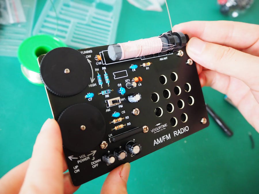
Our project is about soldering the VOGURTIME radio kit. The radio is an old technology, enduring, very classic, I think every person who loves electronics should not miss a radio kit.
Hope the document would be helpful. Thanks for reading.
just start to solder the VOGURTIME AM FM radio kit soon, please check the instruction at below.
To prepare for welding, check the list of components to see if there are any missing parts. Please note that the smaller IC Si4825 has been welded on the circuit board before leaving the factory for your convenience.
Soldering and Installation Steps
1. We’d like to solder the resistors firstly. They could be identified by referring to the picture at below, Or you can use a multimeter to identify them quickly. All the components should not be soldered skips or pseudo soldering.
2. Solder electrolytic capacitors. Please pay attention to the positive and negative direction of the electrolytic capacitor, insert the long pin into the hole which marked with +, and insert the short pin into the hole which marked with -, as Soldering ceramic capacitors and disc capacitors, they don't have polarity, so don't need to pay attention to the positive and negative.
3. don't forget to install the switch and crystal oscillator. This 32.768KHZ quartz crystal oscillator will increase the system stability, improve accuracy and anti-interference.
4. Then solder the IC TA7368PG, please pay attention to the right direction. The side which missing corners corresponds of it should be install to the side with more white areas on the PCB board. Solder the joints of the IC chip would quick and gentle, you don’t want to break it with heat.
5. Next, install the variable resistor VR1, VR2 and the cover parts.
5.1> Please pay attention to VR1 and VR2 position,
5.2> In order to looking good, we can install four small metal pins to fix VR1 and VR2, However, we found that it is difficult for some friends to install these small pins. These pins are not necessary, so choose to fix VR1 and VR2 directly by soldering the two side parts would be good too!
5.3> Back to the front of the PCB board, put the cover turning parts on the VR1 and VR2, then use a cross screw and 2 x 5 mm nickel plating to fix them.
6. Let’s install the speaker right now. First, we need to fix the speaker on the back of the PCB board with the metal parts and screws. Next solder the wire of the speaker on the PCB board. Please note, don’t need to pay attention to the positive and negative poles of it because of using one speaker.
7. Install the two antennas. Put the AM tuning magnetic rod corresponding to the mark on the PCB into it, and then only need to assemble 4 solder spots on the back. Use a screw to securely mount the FM antenna on the back of the PCB and then straighten the antenna as much as possible.
8. Almost done! 😊 Install the battery case. We firstly install the copper columns on the corresponding PCB holes. Then fix the battery case on the columns with screws. Solder the battery case wires to the PCB. Please note that the red wire should be soldered on the corresponding PCB pad marked with +, the black wire should be soldered on the PCB pad marked with -.
9. Excited timing! Let’s put two AA battery into the case for first test, please make sure the batteries have enough power. Then turn the VR2, when you listen the click sound that means it is powered on. Then turning the VR1 gently to receive the radio station, at this time, the VR2 could be used to adjust the voice up and down.Try to switch to change AM to FM or the opposite way.
Enjoy the AM FM radio kit!


Comments
Please log in or sign up to comment.