This project was part of the Lane Tech HS Physical Computing Lab course. I created this project as part of the Home Automation / IoT project. To fit these requirements, I made a device that is turned on by a master control switch using the Blynk App, and that also turns the lamp on if it gets dark.
TinkercadThe first thing I did was learn what the different ports of a relay are and what they mean (COM, NC, NO, VCC, GND, and IN). After this I created an online Tinkercad project using the relay they provided. It was a little different than the one I owned, but it helped me understand how relays worked.
The next step in the project was to hook up the actual relay I would be using. To do this I inserted positive wires into NO (Normally Open) and COM (Common), then I hooked these up to the LED as seen in the picture below. I connected IN (Input) to pin 11 on the Arduino (I used the Arduino because it doesn't require a wifi connection), I connected GND (Ground) to ground, and I connected VCC to 5v. All this did was turn the LED on. I connected the Arduino to my computer to power it.
The next step in the project was to essentially take apart the extension cord. To complete this project you have to cut through the positive side of your extension cord. On most new extension cords the positive side is smooth while the neutral side has grooves. If the two wires in your extension cord are the same, the larger prong is neutral and the smaller one is positive. After figuring out which side of your extension cord has power running through it, you want to cut only that wire in half, and then wire-strip (stripping away the protective casing to expose the wire) both sides. After cutting them in half you'll want to twist the wires as tight as you can and then pre-tin them completely. This means covering all of the exposed wire in solder.
The next step in the project is to connect the wire to relay. The half of the cord leading to the prongs is connected to NO and the other half is connected to COM. Make sure you're exposing as little wire as possible.
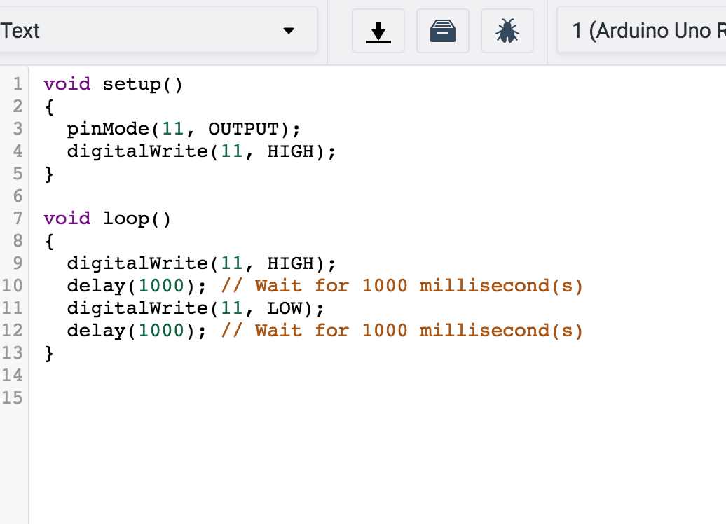
After this you once again connect IN to pin D6, connect GND to ground, and connect VCC to 3.3v, all on the Photon. Upload the code below and listen to your relay, if you have the same one I have you should be able to hear it clicking between closed and open. The Photon automatically sets output pins to LOW, so if you want your relay to be "off" when you start, make sure you set D6 to HIGH. Be careful with the relay, if you touch the bottom it will shock you.
When you are completely sure everything works, you can plug the extension cord connected to your relay into the wall, and plug in your lamp on the other side. Make sure your lamp is turned on. This part is the most dangerous part of the project so be extremely careful. Once you plug into your Photon, assuming you have not flashed any new code, it should turn your light on and off.
BlynkThe next step in the process is to connect your code to Blynk. To do this simply create an account on the Blynk app and create a new project. Make sure to email your authorization code to yourself, you'll need it to connect your Photon to the app. For our project we're going to create one button, and have it be digital button D6. Make sure the button is on switch mode. You will also need to download the Blynk library to your particle photon code. The following code will allow your Blynk app to turn your relay on and off.
The next step in the project is to connect a photocell to your project. A photocell is pretty simple to set up. You want to connect one side of the photocell to A0 (Analog Pin 0). On that same side you'll want to connect it to aa resistor around 10kΩ and ground. The other side of your photocell should be connected to VIN
After connecting your photocell, you'll want to read the voltage coming from it, and compare it to whatever the normal light in your room is (your Dark Threshold). If it is darker than your threshold the light turns on and vice versa. When this code is flashed, your light should turn on when you cover your photocell with your finger.
The final step for setting up the hardware side of your project is making your Blynk button be a "master switch." This means nothing will work or turn on unless your button is switched on. To do this you'll need to change your button from digital D6 to Virtual V0, and flash the following code. The virtual pin allows you to read the value from your Blynk button.
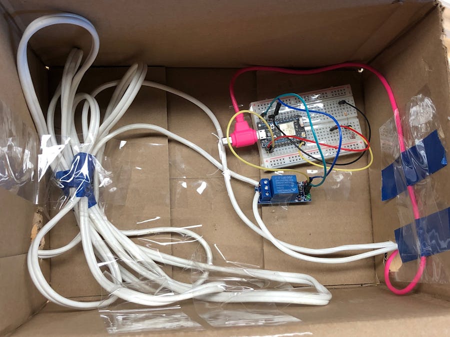
The final step in this project is to create an enclosure that can replicate turning the lights on and off, or plug in the project in your room. Since I had to present this in my classroom, I used a box that could become a "dark room" when the lid was closed. I used an exacto knife to cut two holes in the sides so that the two sides of the extension cord could slip through. Lastly, I taped down the breadboard and relay.
And with that, you're done! Hope you enjoy your new device :)


_3u05Tpwasz.png?auto=compress%2Cformat&w=40&h=40&fit=fillmax&bg=fff&dpr=2)
Comments
Please log in or sign up to comment.