This Printed Circuit Board project is sponsored by JLCPCB. Please visit https://jlcpcb.com/RAT to order your PCB.
The MCP23017 PCB consists of 8 16-Bit I/O Expander with Serial Interface MCP23017 chips.
What is an MCP23017 chip?
It is an integrated circuit (IC) which is an extension of input or output (IO) pins of a microcontroller using the I2C serial communication protocol. It uses the SCL and SDA communication line between the MCP23017 and a microcontroller such as an Arduino or a Raspberry pi. Some of the microcontrollers have a limited number of IO pins, as such, an IO extension like MCP23017 is needed.
There are SCL and SDA communication pins on the MCP.
3 address pins to configure the address of the MCP, which can provide up to 8 MCP23017 for a microcontroller. The address is indexed from 0 to 7, using digital logic to set the address. The Most Significant Bit (MSB) is the A2.
There is an active low reset on the MCP, which a logic low is needed to reset the MCP.
There are 2 interrupt pins on the MCP.
There are 16 IO pins on a single MCP, which are A0 to A7, B0 to B7. The A0 to A7 are IO pins 0 to 7 and B0 to B7 are IO pins 8 to 15.
The AB1 for MCP1, the bottom is pin GPIO1A, the top is pin GPIO1B.
Note that the SDA/SCL, SDA occupies the left column and the SCL occupies the right column.
For this PCB, we will use the CH340 USB to TTL converter for power.
For this coding project, we will use the Adafruit_MCP23017 library, which is available on the Arduino IDE. There are 2 Arduino projects.
For the LED bar circuit, we will blink the LEDs with blink without delay, using the millis() function. We will need 8 of them. It is used to check whether the MCP23017 is working.
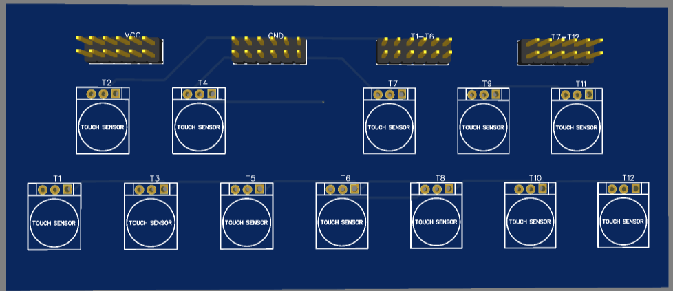
For the piano circuit, each PCB consists of 12 touch sensor keys C to B. We will need 8 of them to create C1 to B8.
Once again, I would like to thank JLCPCB for sponsoring this project. Please order your PCB at https://jlcpcb.com/RAT.


_wzec989qrF.jpg?auto=compress%2Cformat&w=48&h=48&fit=fill&bg=ffffff)


Comments
Please log in or sign up to comment.