


Hardware components | ||||||
| × | 1 | ||||
| × | 1 | ||||
 |
| × | 1 | |||
_ztBMuBhMHo.jpg?auto=compress%2Cformat&w=48&h=48&fit=fill&bg=ffffff) |
| × | 1 | |||
Software apps and online services | ||||||
 |
| |||||
Hand tools and fabrication machines | ||||||
 |
| |||||
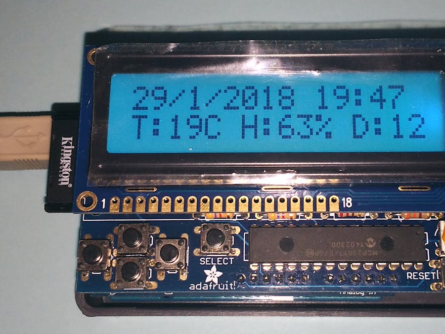
I used to work with old mechanic devices that registered the temperature and humidity in computer rooms. Those devices use a piece of graduated paper and two different pens to write a graph of temperature and humidity over time.
That kind of device had several problems associated to the technology used:
They have to be calibrated regularly,
The pens have to be changed regularly
The paper have to be changed regularly
The data have to be stored in paper dossiers if you want long time history.
As today we have access to cheap microcontrollers, cheap and reliable sensors, cheap RTCs, we can measure data, put a timestamp and easily store data on an SD card, that can store years of information. That idea impelled me to start this project that can replace those old machines.
For this project I used
- The Arduino Uno R3,
- The ADAFRUIT ASSEMBLED DATA LOGGING SHIELD FOR ARDUINO,
- The LCD SHIELD KIT W/ 16X2 CHARACTER DISPLAY also from ADAFRUIT
- The temperature and Humidity sensor DHT11
- As an option I used an LDR to measure ambient light. Sometimes is Important to know if lights are on or off or if case is open, for how long etc...
- As a second option I also record the value of external voltage,using a voltage divider, to detect power failures.
The Adafruit Data Logger Shield can do most of the work, and keep the project simple, because it contains the RTC (Real Time Clock), The SD Interface and the prototyping area. This area is the place used to mount the Sensor DHT11 and the optional light and voltage sensors.
SD Data Logger – pins used
Digital:
02 – DHT11 sensor
03 – Green LED
04 – Red LED
10 – Output - SD CS – SD Library
11 – SD MOSI
12 – SD MISO
13 –SD CLK
Analog:
A0 – Vin Voltage measurement
A3 – Light Sensor (LDR)
A4 – I2C (RTC)
A5 - I2C (RTC)
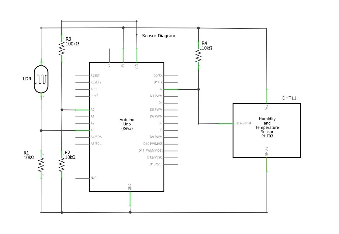
For humidity and temperature sensor I used DHT11, wich is cheap. This part have a 5% humidity and 2ºC temperature tolerance. If you need better accuracy , use DHT22 instead, wich have a tolerance of 0.5ºC (Need diferent library).
For information about libraries and examples about using these DHT sensors, I recommend reading:
The optional Light sensor is a LDR connected between 5V and pin A3. From pin A3 to ground connect a 10K resistor, forming a voltage divider. The voltage present at pin A3 is variable depending on ambient light intensity.
The Vin sensor is comprised of a voltage divider composed by a resistor of 100k and another of 10k. The 100k is conected between Vin and A0 and the 10K conected between A0 and ground.
Display:
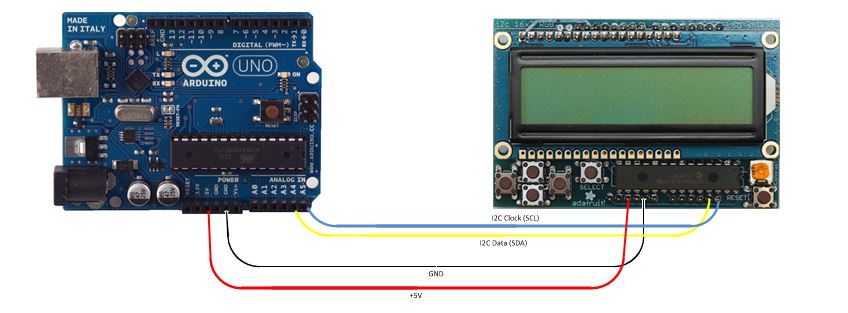
I chose "RGB LCD Shield
" display kit from Adafruit because I can have a LCD display and 5 buttons, using only the 2 pins of the Arduino's I2C (and of course the power lines). The main objective was to save Arduino input/output pins for other purposes.
The kit itself is easy to assemble, just solder all the components in the right place. This kit is a shield and mounts on top of Arduino Uno, so hardware connection is not a big problem. Just sits on top. If you prefer to put the display elsewhere, the connection is also easy. You just need two I2c wires, plus power lines (+5/Gnd).
For more information about this kit and libraries needed, please refer to:
https://learn.adafruit.com/rgb-lcd-shield
https://cdn-learn.adafruit.com/downloads/pdf/rgb-lcd-shield.pdf
Temperature and humidity Sensor DHT11 connections


Comments
Please log in or sign up to comment.