This project was born as a school project. Among the several possible projects, we chose to build the traffic lights controlled by Arduino, to increase our knowledge about this platform. We never used Arduino before, so it was a real challenge. We were asked to use an industrial controller instead, so we decided to build the circuit in a way that can be controlled by both. In Hardware terms, the main difference between the two controllers is voltage output. So we have a DB25 female with different pins for Arduino and for the controller. We use different cables for the Arduino and for the controller that use the different DB25 pins. The pins are connect to the LEDs with resistors of different value. For Arduino we use 220 ohm resistors, for controller 2200 ohm.
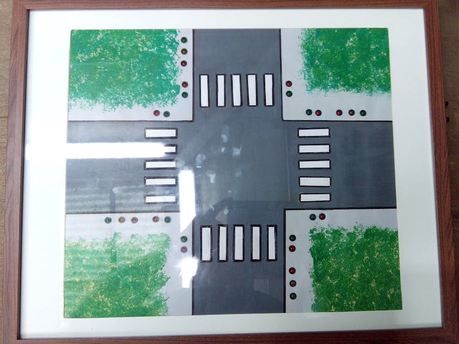
We wanted a good looking device, that can be part of a living room decoration. We decided to use a frame to enclose the circuit and build a live painting of a two-street crossing with semaphores. You can see in fig.1 the frame we used to build the project.
As this project should look like a painting, I asked a little help from my friend Cristina, and we ended up with the lovely painting shown in fig. 2
The space behind the frame was used to do the wiring, as shown in fig 3. To protect the wiring, the back was closed.
The final result, as shown in Fig. 4, was a nice wood frame, containing a live painting, with lights that go on and off. The system starts with blinking yellows, until someone presses one of the 2 pushbuttons. After that, the system starts its normal operating mode of a traffic lights system.
In order to be also controlled by an industrial automaton, we used an old printer cable to do the wiring, as shown in Fig. 5.
To be controlled by Arduino, we used another printer cable to do the wiring needed for Arduino, as shown in Fig. 6.
In Fig. 7 you can see the Arduino connection details.
The Arduino input and output port mapping is the following:
Outputs:- Red (STREET 1) Digital Output 0
- Yellow (STREET 1) Digital Output 1
- Green (STREET 1) Digital Output 2
- Red (STREET 2) Digital Output 3
- Yellow (STREET 2) Digital Output 4
- Green (STREET 2) Digital Output 5
- Pedestrians Red (STREET 1) Digital Output 6
- Pedestrians Green (STREET 1) Digital Output 7
- Pedestrians Red (STREET 2) Digital Output 8
- Pedestrians Green (STREET 2) Digital Output 9
- Pedestrians request (Street 1) Digital input 10
- Pedestrians request (Street 2) Digital input 11
The DB 25 pin socket had the pinout as Illustrated in Fig 8.
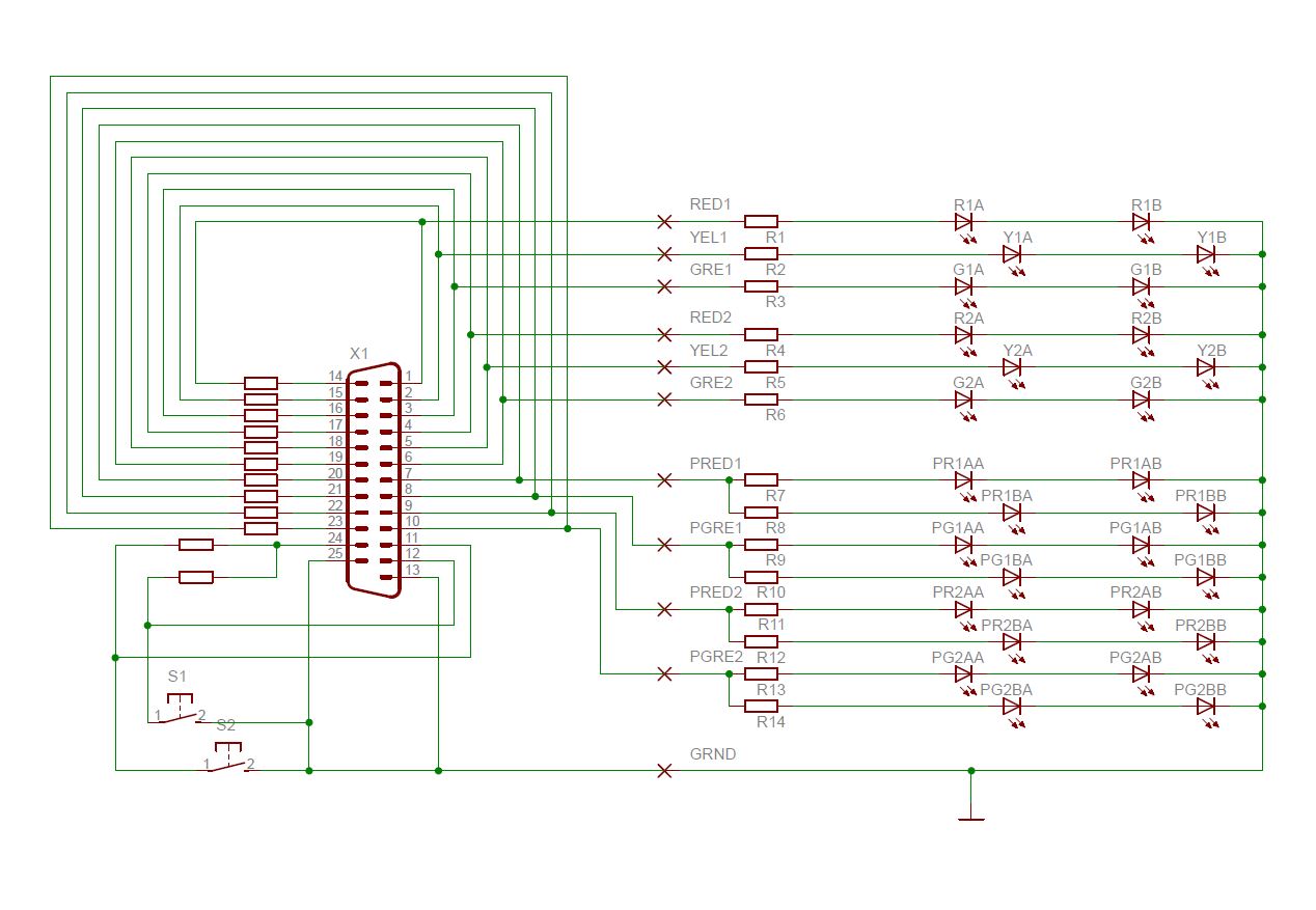
Fig. 9 shows the circuit Diagram of this project
This is an easy to understand circuit, where the LEDs of the same color in the opposite side of each street, are connected in series. This permits to use less Arduino output current, than the parallel option.
The wiring can be a little time consuming, so a little patience is needed.
Hope you enjoyed this project. We had fun building it.
The Team:
Luís Sousa, Emanuel Carpinteiro, Pedro Mealha


_ztBMuBhMHo.jpg?auto=compress%2Cformat&w=48&h=48&fit=fill&bg=ffffff)


Comments
Please log in or sign up to comment.