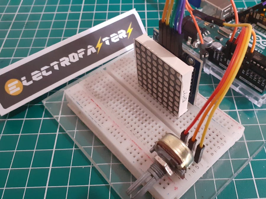
To continue presenting the value of a potentiometer with another device, previously I used only one line of LEDS, now use one of my components that is very common in programming projects: 8x8 Matrix LEDs.
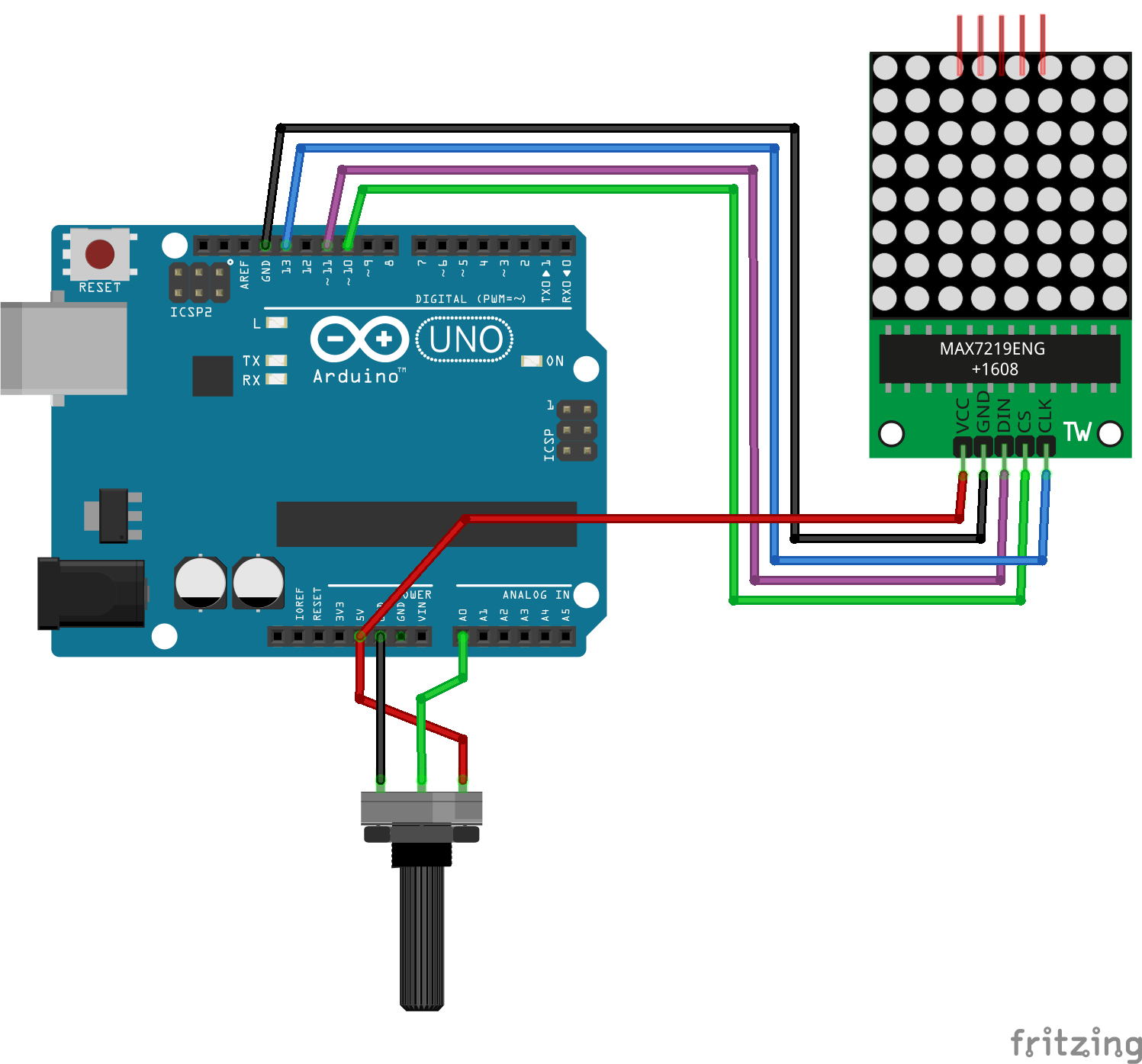
DiagramWhat I love about the LED matrix module is that its connections are very simple and easy to establish, I recommend using the module with the MAX7219 chip not only because of its library but also because of the considerable reduction in cables and extra resistors.
The library used for this representation is LedControl.h, it is one of the most common among all existing ones and can be installed using the standard Arduino library install procedure. Before changing any text in the code, always perform a test, for this I used the following example from the library: LCDemoMatrix.ino
Representation with the matrix of LEDsSince the matrix has the dimensions 8x8, I can use a very simple mathematical calculation in a similar way as in my previous presentation with the 8 LEDs.
Let's remember that we don't have to get complicated in the way of calculating the value if we have the MAP function:
int scale = map(value, 0, 1020, 0, 8);The interesting aspect is how to represent the value with the 64 LEDs of the matrix, even you could make a change and tell us. I used a simplified representation: A column of LEDs is activated based on the resulting value of scale.
The idea.To represent the value of the potentiometer, we can use many combinations of LEDs that the 8x8 matrix can allow us, including an increasing or decreasing scale, in fact up to point by point of the 64 available LEDs, but to simplify the process, I only take the value of the scale variable and activate the corresponding column of LEDs. Here I use the hexadecimal values 0x00 (OFF) and 0xff (ON) to turn the column of LEDs on or off. There are several websites with very interesting editors such as: Xantorohara and Gurgleapps.
Explanation of magicWe start by including the library, naming the required pins and setting up the matrix control object.
#include <LedControl.h>
int DIN = 11;
int CS =  10;
int CLK = 13;
LedControl lc=LedControl(DIN,CLK,CS,1);
In the setup we establish the initial characteristics of the matrix.
void setup(){
    lc.shutdown(0,false);
    lc.setIntensity(0,15);
    lc.clearDisplay(0);
}
We will create a function to activate each column of LEDs.
void printByte(byte character []){
    int i = 0;
    for(i=0;i<8;i++){
        lc.setRow(0,i,character[i]);
    }
}
En el loop creamos un vector para apagar los LEDs, leemos el valor del potenciómetro e interpolamos entre 0 y 8, reasignamos el valor HEX para acitvar los LEDs y llamamos a la función para presentar en la matrix.
In the loop we create a vector to turn off the LEDs, we read the value of the potentiometer and interpolate between 0 and 8, we reassign the HEX value to activate the LEDs and we call the function to present in the matrix.
void loop(){
    byte cero[8] = {0x00,0x00,0x00,0x00,0x00,0x00,0x00,0x00};
    int value = analogRead(A0); // read of potentiometer value
    int scale = map(value, 0, 1000, 0, 8); // map function to get brihtness
    for (int i=0;i<scale;i++){
        cero[i] = 0xff;
    }
    printByte(cero);
    delay(100);
}It is interesting that a numerical value can be represented graphically with the LEDs that are arranged in a matrix, of course it is convenient to use the known libraries or create one if necessary. It is remarkable to remember that the representations with lights allow to attract the attention of any spectator. I hope that the information that I have presented to you, despite its simplicity, can help you with your projects, of course there is much to explore with the matrix and multiple ways to generate, if you have something, please share your ideas in the comments.


_ztBMuBhMHo.jpg?auto=compress%2Cformat&w=48&h=48&fit=fill&bg=ffffff)


Comments
Please log in or sign up to comment.