
Hardware components | ||||||
| × | 2 | ||||
 |
| × | 1 | |||
| × | 1 | ||||
 |
| × | 2 | |||
| × | 1 | ||||
 |
| × | 1 | |||
 |
| × | 1 | |||
| × | 1 | ||||
| × | 1 | ||||
| × | 1 | ||||
 |
| × | 5 | |||
 |
| × | 2 | |||
Hand tools and fabrication machines | ||||||
 |
| |||||
 |
| |||||
When I was a kid I always loved the idea of owning an RC boat and taking it out for a spin on a lake somewhere. Now that I have the necessary technical training and resources I decided to build my own. I specifically chose a fan boat so that I didn't have to worry about waterproofing my electrical components.
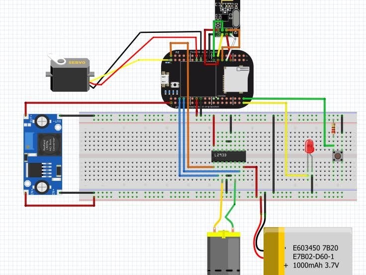
The Current DesignThe finished device is made up of two systems: the remote control and the components intended to be installed within the boat. The operation of the device is relatively simple. First, both Pocket Beagles need to be powered up, the onboard one through the battery and the remote control one through a USB connection to a computer. Once the green LED on the onboard section lights up, the boat is ready to be controlled. Then the user simply has to move the KY-023 joystick in the desired direction to achieve the intended motor and servo response. When the joystick is oriented correctly (pins are facing away from the user), vertical movement causes the dc motor to spin and horizontal movement turns the servo. When the user is finished, holding down the button on the onboard section will end the program, indicated by the green LED turning off. Shown below is a video of the device in operation.
Pocket Beagle Pin LayoutThe KY-023 joystick has 5 pins: 5V, GND, VRX, VRY, and SWITCH. The 5V pin should be connected to the SYS VOUT pin "P1_24" and the GND to "P1_24". For this project, I had no use for the Switch so I didn't connect it but generally it should be wired to a GPIO pin of your choosing. VRX and VRY give out voltage values of up to 5V based on the movement of the joystick and are connected to analog in AIN1 (P1_21) and AIN2(P2_23) respectively. In order to avoid overloading the analog input pins which can only take 1.8V, the connections to VRX and VRY must first be passed through a voltage divider circuit made up of 2 1k ohm resistors (shown below). The joystick is connected to a 3D printed holding platform (file provided below) with M3-10 bolts.
To set up the resistor and transmitter connect GND to GND (P2_21), VCC to 3.3V (P2_23), CE to GPIO48 (P2_24), CS to GPIO46 (P2_22), SCK to CLK (P2_29), MOSI to MOSI (P2_25), and MISO to MISO (P2_27). IRQ is an optional pin and does not have to be wired up for basic operation. Additionally, if you choose to use SPIO0 instead of SPIO1 then it is important that you make the necessary changes in the initialization functions for both the transmitter and receiver.
After wiring up the transmitter and receiver, you need to power up the Pocket Beagle, connect it to the internet, and install the following.
sudo pip3 install circuitpython-nrf24l01This should be imported into the receiver and transmitter code as such:
from circuitpython_nrf24l01.rf24 import RF24In order to allow connection at greater distances, increase the pa_level in the code for both the transmitter and receiver.
The DC motor is powered by the dual H-bridge L293D motor controller. The L293D allows the user to apply voltage to the motor from either direction and therefore spin the motor both clockwise and counter-clockwise. As this design employs one DC motor, only half of the motor controller pins are needed. However, another motor could be added to the system with little difficultly. The Enable 1, IN 1, and IN2 pins are connected to GPIO 59 (P2_2), GPIO 5 (P1_6), and GPIO 2 (P1_8) respectively. It is important that the Enable pin is connected to a GPIO pin with an initial state of LOW so that the motor does not automatically run during boot-up of the Pocket Beagle. The 3.3V pin (P1_14) of the Pocket Beagle should be connected to the power rail of the breadboard. VCC is connected to the 3.3V power rail and Vmotor should be connected to the 12 V battery. The OUT1 and OUT2 pins should be connected to either side of the DC motor with soldered wires. The GND pins on either side of the L293D should be connected to the breadboard ground rail which is connected to the GND pin P1_16 on the Pocket Beagle. The logic for the motor controller is shown below.
Pin 6 (IN1)       Pin 8 (IN2)      Pin 2 (Enable1)  Result
High              Low              High               Motor spins one direction
Low               High             High               Motor spins other direction
High              High             High               Stopped
Low               Low              High               Stopped
X X Low StoppedThe onboard Pocket Beagle is powered locally through the 12V battery used for the DC motor. However, the power must first pass through a 12V to 5V regulator to protect the Pocketbeagle. The 12V should be connected to one of the breadboard's power rails. The VIN+ pin of the regulator should be connected to this rail while the VIN- pin should be connected to the breadboard's ground rail. A USB should be used to connect the regulator to the Pocket Beagle. Coming from experience, triple check your wiring before connecting the battery as one misplaced wire can fry your Pocket Beagle.
Additional ComponentsServo
- VCC connected to SYS VOUT (P2_13)
- GND connected to SYS GND (P2_15)
- Signal connected to PWM1A (P2_1)
- Ensure that you install the servo arm perpendicular to the length of the casing so that the steering functions correctly.
Button
- Connected to GND rail of the breadboard.
- Other side has pull up resistor of 1k ohm connected to the 3.3 V power rail.
- Same side is connected to GPIO 110 (P1_36)
LED
- Anode is connected to breadboard GND rail
- Cathode is connected to GPIO 88 (P1_35)
Once all libraries and code are installed in the Pocket Beagles, enter the code below for both systems after making a directory called logs under the cloud9 directory.
sudo crontab -e
#Once in the crontab
@reboot sleep 30 && sh <your run file path> >/var/lib/cloud9/logs/cronlog 2>&1
Then reboot your device.
This makes it so both the remote and onboard systems run automatically upon booting up the Pocket Beagle.
Moving forward I plan on adding further functionality and complexity to the code to improve the operation of the device. I also plan on switching out the DC motor for a smaller model. The next biggest step is to design the fan boat on SolidWorks and 3D print. From there I will install the components and test out the boat in the nearest body of water.


Comments