


Hardware components | ||||||
| × | 1 | ||||
 |
| × | 1 | |||
 |
| × | 1 | |||
Software apps and online services | ||||||
| ||||||
What we are going to do is to turn ESP8266 WiFi module into a web server that shows a simple console to control an LED. A console is going to be an HTML page that sits on ESP8266. It is going to have a piece of JavaScript code that makes a RESTful call to the ESP8266 module to either set or get LED status. In the ESP8266 firmware code, we are going to write a piece that handles a RESTful call.
For writing a firmware code, we are going to use Mongoose IoT, which is an open source framework for developing professional-grade connected solutions. Mongoose Firmware helps us to run a web server and connect to the WiFi network.
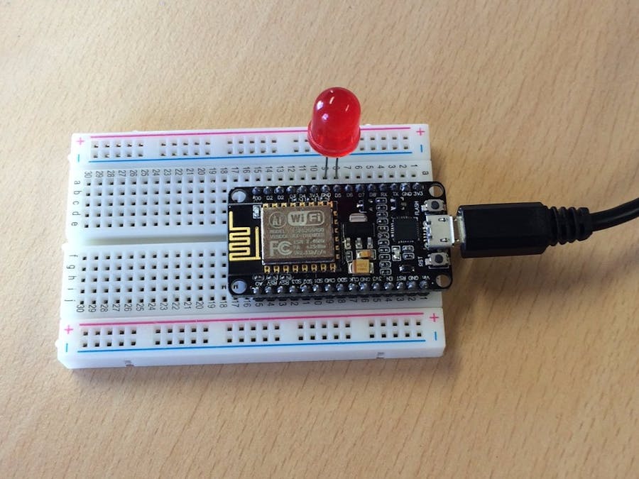
Hardware setupConnect LED to the pins marked D5 (which is GPIO 14) and GND on the NodeMCU, just like it is shown on the cover image.
Writing a RESTful server on ESP8266Once a NodeMCU board is connected to your computer via the USB cable, it's time to write the firmware. Download firmware management tool miot from https://mongoose-iot.com/downloads.html .Create an empty directory, and start a command line console in that directory. Run the following miot commands to login to Mongoose IoT cloud-based build system and initialise firmware directory:
miot auth login
miot fw init --arch esp8266
That is going to create necessary files and directories. Now let's write a RESTful server. Open src/app.c in your editor and copy-paste this code in:
#include "fw/src/mg_app.h"
#include "fw/src/mg_gpio.h"
#include "fw/src/mg_mongoose.h"
static int s_gpio_pin = 14;
static void get_handler(struct mg_connection *c, int ev, void *ev_data) {
 if (ev == MG_EV_HTTP_REQUEST) {
   int state = mg_gpio_read(s_gpio_pin);
   mg_printf(c, "HTTP/1.0 200 OK\r\n"
             "Content-Type: application/json\r\n\r\n"
             "{ \"state\": %d }\n", state);
   c->flags |= MG_F_SEND_AND_CLOSE;
 }
 (void) ev_data;
}
static void set_handler(struct mg_connection *c, int ev, void *ev_data) {
 struct http_message *hm = (struct http_message *) ev_data;
 if (ev == MG_EV_HTTP_REQUEST) {
   int result, state = 0;
   sscanf(hm->body.p, "state=%d", &state);
   result = mg_gpio_write(s_gpio_pin, state);
   mg_printf(c, "HTTP/1.1 200 OK\r\n"
             "Content-Type: application/json\r\n\r\n"
             "{ \"result\": %d }\n", result);
   c->flags |= MG_F_SEND_AND_CLOSE;
 }
}
enum mg_app_init_result mg_app_init(void) {
 mg_gpio_set_mode(s_gpio_pin, GPIO_MODE_INOUT, GPIO_PULL_PULLUP);
 mg_register_http_endpoint(mg_get_http_listening_conn(), "/get", get_handler);
 mg_register_http_endpoint(mg_get_http_listening_conn(), "/set", set_handler);
 return MG_APP_INIT_SUCCESS;
}
Now, build the firmware by running
miot cloud build
Built firmware is save as build/fw.zip. Let's flash it:
miot dev flash -fw build/fw.zip -port /dev/ttyUSB0
Note that the port /dev/ttyUSB0 is typical for Linux systems. On Windows, you might be using COM1, on MacOS - /dev/cu.SLAB_USBtoUART. When the device is flashed, configure it to join the WiFi network:
miot dev config set -port /dev/ttyUSB0 wifi.ap.enable=false wifi.sta.enable=true wifi.sta.ssid=WIFI_NETWORK_NAME wifi.sta.pass=WIFI_PASSWORD
Getting configuration...
Setting new configuration...
After that, find out what IP address ESP8266 is using:
$ miot dev call --port /dev/ttyUSB0 /v1/Config.GetNetworkStatus
{
  "wifi": {
    "sta_ip": "192.168.1.39",
    "ap_ip": "",
    "status": "got ip",
    "ssid": "WIFI_NETWORK_NAME"
  }
}
Now, ESP8266 can talk to the Internet! And it runs the RESTful server to turn an LED on or off. Let's use curl command line utility to test it - turn an LED on (take the IP address from the output of the previous command):
curl -d state=1 http://192.168.1.39/set
{ "result": 0 }
It turns an LED on!
We can query the current status, and turn it off:
curl http://192.168.1.39/get
{ "state": 1 }
curl -d state=0 http://192.168.1.39/set
{ "result": 0 }
Okay, now we can talk to the ESP8266 via a RESTful API. Good. Let's build a handy web page. Create a filesystem/console.html file, and copy/paste this code in:
<html>
<head>
<script type="text/javascript" src="https://cdnjs.cloudflare.com/ajax/libs/jquery/1.3.2/jquery.js"></script>
</head>
 <h1>Hello from ESP8266!</h1>
 <p>LED state: <span id="state"></span></p>
 <input type="checkbox" id="control"> Set state</input>
 <script>
   $(document).ready(function() {
     // Query LED state every second
     window.setInterval(function() {
       $.get('/get', null, function(data) {
         $('#state').html(data.state);
       }, 'json');
     }, 1000);
     $('#control').change(function() {
       var state = $(this).is(':checked') ? 1 : 0;
       $.post('/set', 'state=' + state);
     });
   });
 </script>
</html>
The design of this page is intentionally minimal, just to demonstrate the idea. Now let's copy this file to the ESP8266 module:
miot dev fs put -port /dev/ttyUSB0 filesystem/console.html
And point the browser to this file on the module:
That's it! Note that Mongoose Firmware supports TI CC3200 module as well, so the same sequence of steps is possible with CC3200. Mongoose Firmware supports virtually any networking protocol - plain TCP, UDP, HTTP, WebSocket, MQTT, CoAP, etc. Stay tuned for the next projects!


Comments
Please log in or sign up to comment.