


Hardware components | ||||||
_ztBMuBhMHo.jpg?auto=compress%2Cformat&w=48&h=48&fit=fill&bg=ffffff) |
| × | 1 | |||
| × | 1 | ||||
| × | 1 | ||||
| × | 1 | ||||
 |
| × | 1 | |||
Software apps and online services | ||||||
 |
| |||||
| ||||||
 |
| |||||
Hand tools and fabrication machines | ||||||
 |
| |||||
 |
| |||||
Our article concerns the design of a breathalyser: we will study the concept, the choice and calibration of the sensor, the addition of a buzzer and finally the use of an LED bar. We will see how to produce the electrical circuit and the pcb, and a container that we can build using a 3D printer or plywood. Let's begin!
The first operation to be carried out will be the configuration of the ethyl sensor MQ303A, capable of perceiving concentrations between 20 and one thousand parts per million. We chose to use the version offered by Seeed Studio, at less than 9$, as it is quite well documented both in the project sheet and in the configuration parameters.
The sensor has a four-pole grove connection, 2 for the 5 volt power supply and 1 for the analog signal to be connected to an analog pin on the Arduino, and one to drive the preheating of the sensor. When fully operational it will consume approximately 120 miliamps.
It is necessary to pre-heat the sensor for at least 48 hours before first use.
But how does such a sensor work? The sensor provides a resistive output inversely proportional to the alcohol concentration: the piloting circuit, very simple, only requires a resistance. A simple ADC module is sufficient to perform the reading.
An air reading is initially taken for calibration, then the capsule is placed in proximity to the alcohol vapors and the ratio of recognized particles crossing the electrified metal surface is calculated.
#define PIN_RISCALDATORE 15

void setup() {
  Serial.begin(9600);
  pinMode(PIN_RISCALDATORE, OUTPUT);
  digitalWrite(PIN_RISCALDATORE, LOW);
}

void loop() {
  float tensione_sensore;
  float Rs_aria;  // Acquisisce il parametro RS in aria
  float valore_sensore = 0.0;

  // --- Richiediamo la media su 100 letture ---
  for (int x = 0; x < 100; x++) {
    valore_sensore = valore_sensore + analogRead(A0);
  }
  valore_sensore = valore_sensore / 100;
  Serial.print("Valore sensore = ");
  Serial.println(valore_sensore);
  // ---

  tensione_sensore = valore_sensore / 1024.0 * 5.0;
  // La tensione è inversamente proporzionale alla concentrazione
  Rs_aria = tensione_sensore / (5.0 - tensione_sensore);
  Serial.print("Tensione sensore = ");
  Serial.print(tensione_sensore);
  Serial.println("V");
  Serial.print("Rs aria = ");
  Serial.println(Rs_aria);
  delay(1000);
}
The first program (see the attachment list) that we show is used to acquire the sensor data and the variables obtained in the pre-heating. As we learned from our Simone, it is possible to use Arduino analog PINs as digital PINs: the link is in description. In the Setup section we activate the serial that allows us to read the values detected by the sensor, and we define pin A1 as digital pin 15. Inside the loop we define our variables for reading: the voltage present on pin A0 of the sensor, the parameter relating to the resistance of the apparatus in free air without alcohol vapors, and the value of the sensor after the transformation of the analog to digital converter. We perform a cycle of readings to statistically weigh the average of the recognized values in free air at best (lines 14 18) then recall the value present on the pin, and transform it into a digital value between 0 and 1.023. Finally we print the values on the serial monitor.
The sensors we have examined seem to interact in some way with the Arduino serial, so much so as to raise some operational problems.
We managed to make everything work with the following procedure:
- compiling the code,
- inserting the USB cable,
- launching the Arduino ide,
- checking the presence of the communication port,
- selecting through the menu tools-> port-> requested port (even if it is already selected),
- double click on the Arduino reset button,
- upload and launch the code.
Then selecting the serial monitor strictly from the tools menu, because clicking on the magnifying glass leads to an error.
The second program uses the RS_air value calculated by the first: it must be replaced in line 13, and calculates the ratio between resistance in free area and the actual value found. Finally print the value on the serial monitor.
Bringing a glass containing an alcoholic substance close to the sensor, the alcohol particles are immediately recognized, and the values modified.
The time has come to get your hands on the project. In this diagram we can see a "stylized" mq 303A sensor, with the power supply and signal driving contacts, and the relative connections on our Arduino. We also wanted to add a practical buzzer that will sound as soon as the concentration level of alcohol in the air exceeds a certain threshold. What this threshold is depends on the measurements: the alcohol content for human beings is in fact measured in g / liter, while the sensor gives us a value in parts per million. To further complicate things we add that it has a calculation function of the sensor is not linear: it depends on the humidity and that generally the values recognized by the instrument do not vary between 0 and 1023, as normally happens on Arduino, but instead between 500 and 905, thus further reducing the sensitivity (typically 10 bits) of the Arduino.
#define PIN_BUZZER        2
#define PIN_RISCALDATORE 15

int scala = 0;
float valore_sensore;
float tensione_sensore;
float Rs_aria;

void setup() {
  // Serial.begin(9600);

  pinMode(PIN_BUZZER, OUTPUT);
  pinMode(PIN_RISCALDATORE, OUTPUT);
  digitalWrite(PIN_RISCALDATORE, LOW);

  // Pin di pilotaggio dei LED
  pinMode( 3, OUTPUT);
  pinMode( 4, OUTPUT);
  pinMode( 5, OUTPUT);
  pinMode( 6, OUTPUT);
  pinMode( 7, OUTPUT);
  pinMode( 8, OUTPUT);
  pinMode( 9, OUTPUT);
  pinMode(10, OUTPUT);
  pinMode(11, OUTPUT);
  pinMode(12, OUTPUT);

  digitalWrite( 3, LOW);
  digitalWrite( 4, LOW);
  digitalWrite( 5, LOW);
  digitalWrite( 6, LOW);
  digitalWrite( 7, LOW);
  digitalWrite( 8, LOW);
  digitalWrite( 9, LOW);
  digitalWrite(10, LOW);
  digitalWrite(11, LOW);
  digitalWrite(12, LOW);

  // --- Richiediamo la media su 1000 letture ---
  for (int x = 0; x < 1000; x++) {
    valore_sensore = valore_sensore + analogRead(A0);
  }
  valore_sensore = valore_sensore / 1000.0;
  tensione_sensore = (float)valore_sensore/1024*5.0;
  Rs_aria = tensione_sensore / (5.0 - tensione_sensore);
}

void loop() {
  float Rs_gas;
  float rapporto;

  valore_sensore = analogRead(A0);
  tensione_sensore = (float)valore_sensore/1024*5.0;
  Rs_gas = tensione_sensore/(5.0 - tensione_sensore);

  rapporto = Rs_gas / Rs_aria;

  // Definiamo una scala a 10 elementi per gestire il rapporto alcolemico
  scala = 0;
  if (rapporto > 0.8) scala = 0;
  if (rapporto > 0.7 && rapporto < 0.8) scala = 1;
  if (rapporto > 0.6 && rapporto < 0.7) scala = 2;
  if (rapporto > 0.5 && rapporto < 0.6) scala = 3;
  if (rapporto > 0.4 && rapporto < 0.5) scala = 4;
  if (rapporto > 0.3 && rapporto < 0.4) scala = 5;
  if (rapporto > 0.2 && rapporto < 0.3) scala = 6;
  if (rapporto > 0.15 && rapporto < 0.2) scala = 7;
  if (rapporto > 0.1 && rapporto < 0.15) scala = 8;
  if (rapporto < 0.1) scala = 9;

  accendi(scala);
  suona(scala);
/*
  Serial.print("Tensione sensore = ");
  Serial.print(tensione_sensore);
  Serial.println("V");
  Serial.print("Rs_gas = ");
  Serial.println(Rs_gas);
  Serial.print("Rs/R0 = ");
  Serial.println(rapporto);
  Serial.println(scala);

  Serial.println("---");
*/
  delay(2000);
}

void accendi(int n) {
  // Spegne tutti i LED
  for (int i = 0; i < 10; i++) {
    digitalWrite(i + 3, LOW);
  }

  // Accende i LED necessari
  for (int i = 0; i < n + 1; i++) {
    digitalWrite(i + 3, HIGH);
  }
}

void suona(int n) {
  switch (n) {
    case 7:
      for (int i = 0; i < 3; i++) {
        tone(PIN_BUZZER, 220, 200);
        delay(200);
        tone(PIN_BUZZER,   0, 200);
        delay(200);
      }
      break;
    case 8:
      for (int i = 0; i < 4; i++) {
        tone(PIN_BUZZER, 440, 100);
        delay(100);
        tone(PIN_BUZZER,   0, 100);
        delay(100);
      }
      break;
    case 9:
      for (int i = 0; i < 5; i++) {
        tone(PIN_BUZZER, 880,  50);
        delay(50);
        tone(PIN_BUZZER,   0, 50);
        delay(50);
      }
      break;
    default:
      break;
  }
}
Let's see how the Main program works. We have added the definition of pin 2 which is the buzzer, and pin 15 which is the heater that we will need for our sensor. We add in the integer variable, scale, we will then see what it is used for, the definition of the first: sensor_value, sensor_voltage and air resistance. We define the serial, it can also be commented, we define the pin mode, type of writing, we put the heater at LOW so that the sensor starts to work, we define the driving pins for the LED bar, from 3 to 12 are ten, there we define as OUTPUT and set them to LOW. We request a reading on an average of 1, 000 of the sensor value, so that it is current, we start the loop. We define a new resistance value for the gas, and a new float variable for the ratio between the gas value and the air value. We read further, with analogRead(), the value inside the loop, and we define this ratio: if there are no alcohol vapors this ratio will be as close as possible to 1 substantially it deviates very very little. We therefore define a ratio: as long as the ratio is greater than 0.8, then the resistance of the gas is lower but slightly, the scale will be 0. As this value decreases, that is, as the resistance in the presence of ethyl alcohol decreases towards the 'air (we saw earlier that the resistance in the presence of ethyl vapors is lower than air, so this ratio decreases), the more it decreases the more the scale ratio increases. We have the definition between 0 and 9, let's see why. We define two functions, turn on based on the scale value ratio, and sound based on the scale value. This section on serial printing has been inserted mainly for debugging, but we can safely delete it. This way we perform a reading every two seconds.
Now let's see how the function accendi() and the function suona() have been implemented. accendi() does nothing but turn off all the LEDs (n therefore it is worth scale) from 0 to 9 putting them at LOW. Then it turns on all the LEDs ranging from zero to scale-1. We set the values i + 3 to HIGH. I goes from 0 to scale, we have seen that the pins start from 3, so just add 3 to the scale value to turn on the relative pin.
The suona() function is a little more complex: we basically define a switch / case that is activated if the scale reaches 7 8 or 9, in all other cases the function does nothing. What does it do in case of scale = 7? It simply emits a 220 Hz tone, then a low A, three times, 200 milliseconds long, and then resets the buzzer emitter. If instead of seven we have eight, that is a higher scale value, therefore a higher concentration of alcohol, we make four beeps at 440 Hz, therefore an octave higher, for a time of 100 milliseconds instead of 200. In this case, the saturation of ethyl vapors is maximum, so "case 9", we play 5 buzzes, this time at a further higher frequency then an even higher octave. At 880 it is shorter.
Since we can't have enough, and want our project to be usable also by the hearing impaired, we decide to add an LED scale to show us the level of saturation. But instead of using the classic round LEDs we use this module which contains 10 of them.
The casing contains 10 rectangular colored LEDs as in the image. It will be sufficient to connect them to as many Arduino digital pins with the appropriate current limiting resistor, for a splendid interface even for the deaf user.
And for those who are worried about the tide of resistors to connect, here's the news: a network resistor with ten elements plus ground connector, ready for use. This saves new connections and when mounting on the PCB 9 solders and a lot of space.
And here's our prototype. You can see our sensor at the top right, at the top left the socket on which we will mount our LED bar, at the bottom we see the LED bar connected with the network resistor, all connected with our Arduino, and the buzzer at the bottom. left.
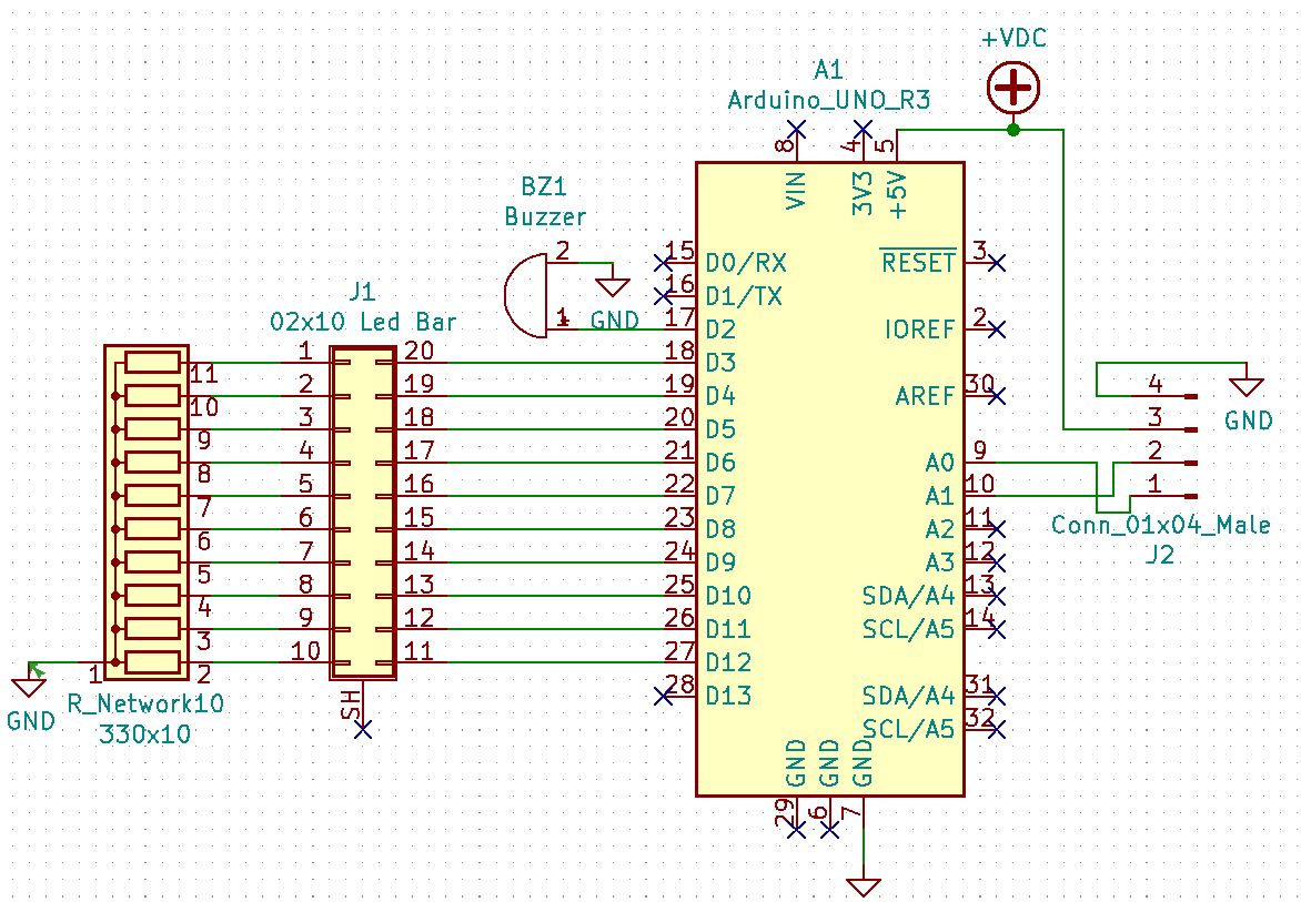
Here instead is represented the wiring diagram of our circuit. We have worked with KiCAD, but it can be easily transformed into any other electronic calculation system. We represented our Arduino, in reality it is its pinout, the buzzer, the resistors, the socket on which we will mount our diode arrai, and a 4-pin connection on which we will connect the sensor.
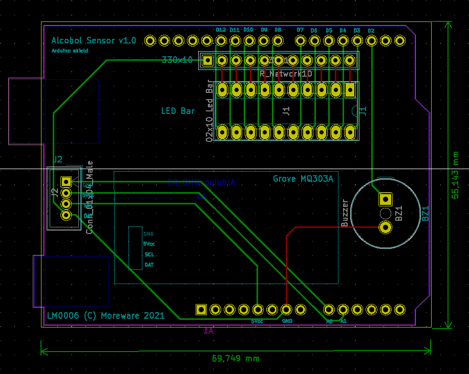
The resulting printed circuit is quite simple: the important thing is to remember that normally the CAD presents it upside down, so we have to perform a 180 degree flip, after which it will be sufficient to connect all the fillings in the current way and we will have our final result.
The KiCAD 3d simulator gives us this result. You can see the section reserved for the MQ303A grove sensor, at the bottom we have our buzzer, we have the socket on which the LED array will be mounted, the array of resistors and a series of holes on which the pins that we will use have been configured for the circuit. Normally they all connect through a multiple connector.
For every DIY activity, the container cannot be missing. We used TinkerCAD to create a possible casing in which to insert our Arduino with the sketch board we just designed. We also designed a hole for inserting the LED bars. At the top we have a hole for the LED bar while the small cone is used to possibly convey the breath when you decide to use the system as a breathalyzer. The STL cards (of the project) are available.
Of course donations to our blog would accelerate the development of other DIY projects of this kind, so keep an eye on it, and please keep the likes coming!
Here is a video explaining the development of the project, dubbed in Italian and English language.


Comments