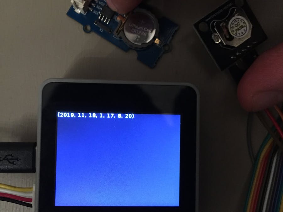
Before we start let's first get clear on what exactly an RTC is. It stands for REAL TIME CLOCK. Anyone who is poked around inside a computer before, will likely have seen a coin cell battery sitting somewhere on the motherboard. What is that doing there, surely it's not powering your computer is it?
One thing that is important to us all is knowing the time, and computers need to be aware of it to. But what happens when we switch off our computers? surely they will not be able to keep the time if they are powered off, and when we switch them back on the time will be inaccurate.
This is where the RTC comes in. That little coin cell battery is keeping a tiny low power consuming chip awake, so it can keep a track of the time even when your computer is off.
Unfortunately the M5Stack doesn't have an RTC, but don't worry it's easy enough for us to add one. There are many low cost breakout boards on the market which feature the chip DS1307 and other similar chips, but for the sake of this tutorial we will simply be focusing on the DS1307.
I have two DS1307 modules, you can use either one whether you have a basic M5Stack with male and female header pins on the base, or an M5GO or Fire with the grove ports. I used the robotdyn rtc module with my M5Stack black https://robotdyn.com/rtc-real-time-clock-ds1307-module.html
It has 5 pins but we only need to use 4 of them, ground and 5v for power and the other two for i2c communication over the sda and scl pins. It has a remaining SQW pin which I assume is for generating a square wave, but I have not tested it. We connect it up to the M5Stack Basic like so:
Alternately if you only have a base with grove ports then you would be better using a grove compatible module such as this one from seeedstudio https://www.seeedstudio.com/Grove-RTC.html both of these modules require a cr1225 coin cell battery to work. Just hook the RTC module up to port A on your M5GO like so:
Now that we have everything hooked up we need to get a library that controls the RTC module. There's an excellent one written by mcauser, who has written a lot of great micropython libraries for various components https://github.com/mcauser/micropython-tinyrtc-i2c
Download and unzip the files, and then transfer them to the flash memory of the M5Stack with Ampy or VScode micropython plugin. If you don't know how to do that see how in one of my video guides. Ampy or VScode
Once we have the ds1307 python module on there we can start to program the I2C module. On mcauser's github he clearly introduces all of the functions in the library https://github.com/mcauser/micropython-tinyrtc-i2c
I just simply set up the device on i2c, created a list containing the current time and then assigned it to the ds.datetime() function. since ds.datetime() is a tuple and lcd.text() doesn't like tuples, I had to do a little bit of a workaround. You can see the code below, if you liked this guide please respect and leave some comment if you get stuck, thanks.
from machine import I2C
from m5stack import *
import ds1307, lcd
i2c = I2C(1, I2C.MASTER, sda = 21, scl = 22)
ds = ds1307.DS1307(i2c)
#enable the osscilator
ds.halt(False)
ds.datetime()

#enter the current time (year, month, date, weekday, hour, minute, second, microsecond)
now = (2019, 11, 18, 1, 16, 20, 22, 0)
ds.datetime(now)
while(True):
    time = ds.datetime()
    lcd.text(0,0,str(time[0:8]),lcd.WHITE)


_1x_bGT19vVAby.png?auto=compress%2Cformat&w=40&h=40&fit=fillmax&bg=fff&dpr=2)


Comments
Please log in or sign up to comment.