Introduction
Airify is an autonomous and self calibrating low cost air quality monitor system that is optimize for remote deployment and production in third world country. Using a solar panel, Airify is able operate continuously for a long period of time , without the need of a power line cable, in the monitoring of temperature, humidity, volatile organic compoumd , carbon dioxide , and methane. Using these metric, Airify going employ machine learning using SensiML platform to build a model to predict the air quality as well and upcoming weather condition of the current area. The goal of this project it to keep the cost down by using non industrial grade sensor and apply SensiML machine learning capabilities to produce a highly accurate air quality value from the sensor data. The predictred air quality value will range from 0-400 using the scale below.
The predicted air quality will be display on a cloud IoT platform so that the user can monitor the air quality remotely without the need to be at the site.
Enclosure Assembly
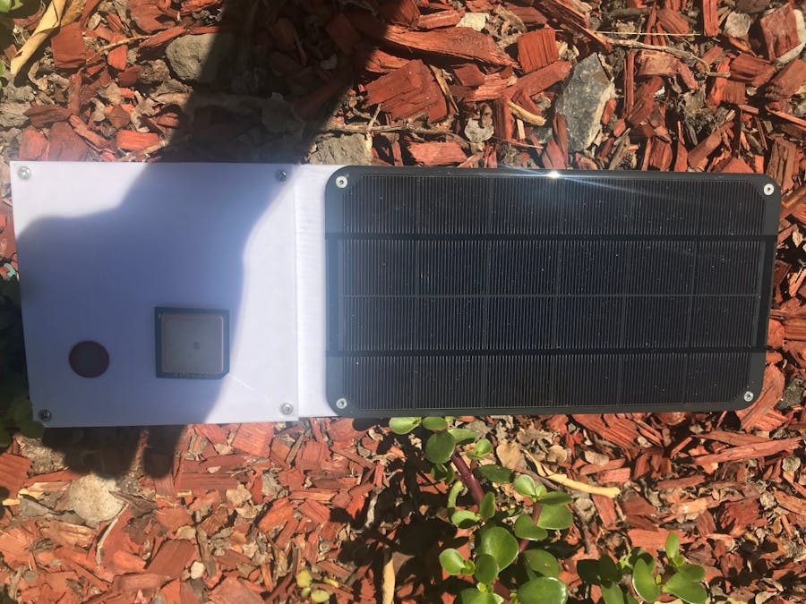
Airify enclosure consist of two simple pieces that is tight fit together and provide space for the user to mount the solar panel for remote monitoring.
First mounted the solar panel on the top piece to the side, then attach 2 15mm stand off on the other side of the solar panel.
Mount the GPS and and the methane sensor as show below on the top piece. Attach wiring from the GPS and methane sensor to the Quickfeather. The put the rest of all the electronic component onto the bottom piece and tight fit the top piece on top of the bottom piece.
Then attach 3 10mm 3m screw onto the four corner of the top piece as show above to tightly secure the enclosure. Then put the rest of all the electronic component onto the bottom piece and tight fit the top piece on top of the bottom piece.
Electronic Wiring
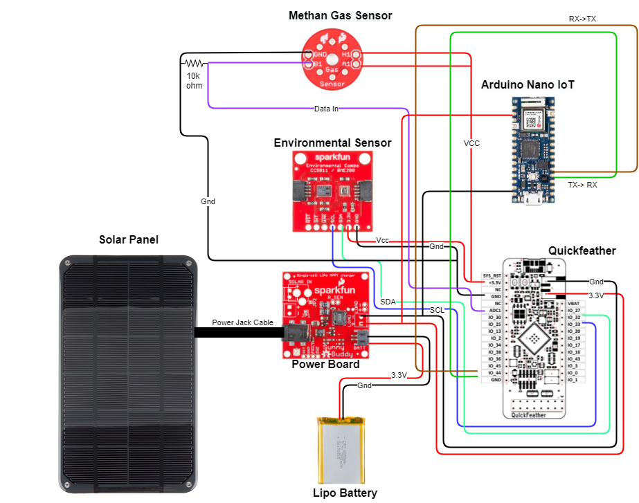
There are two different sensors ( Qwiic Environmental Breakout Board and Methane gas sensor). The Qwiic Environmental Breakout Board use I2C protocol while Methane gas sensor use ACD. There connection to the Quick Feather board is show below.
Next, we have the pinout and connection between the GPS module and the Arduino Iot.
Then, we have the Quickfeather to Arduino Nano connection. The Quickfeather transfer sensor data and air prediction data to the Arduino Nano and the Nano update it to the cloud over Wifi.
Finally, both the Quickfeather and Arduino Nano is power by a Lipo battery via and MPPT Solar Charger. The charger is also hookup to a solar panel which recharge the Lipo battery.
The overall system wiring is show below here with everything connected together.
Capturing Data and Model Training
The qf_ssi_ai_app is going be use as template for the Quickfeather firmware to capture the Qwiic data from I2C and methane sensor data from ADC pin. Firstly we need to import all the necessary library.
Qwicc Environmental Breakout Board : https://github.com/sparkfun/SparkFun_BME280_Arduino_Library/archive/master.zip
https://github.com/sparkfun/SparkFun_CCS811_Arduino_Library/archive/master.zip
Methane Gas Sensor : The native ADC quickfeather api is good enough
This section will only show snippet of code that you will need to change from the template. The first thing is to edit the JSON file and add relevant library in the import inside sensor_ssss.cpp .
#include <SparkFunBME280.h>
#include <SparkFunCCS811.h>
.....
const char json_string_sensor_config[] = \
    "{"\
    "\"sample_rate\":100,"\
    "\"samples_per_packet\":6,"\
    "\"column_location\":{"\
    "  \"Temperature\":0,"
    "  \"TVOC\":1,"
    "  \"CO2\":2"
"}"\
"}\r\n" ;
Then modify the sensor_ssss_buffer_ready() to read in new sensor data and allow it to be capture by SensiML Data Capture Client
//#define CCS811_ADDR 0x5A //Alternate I2C Address

//Global sensor objects
CCS811 myCCS811(CCS811_ADDR);
BME280 myBME280;
...

int  sensor_ssss_acquisition_buffer_ready()
{
    int8_t *p_dest = (int8_t *) &psensor_ssss_data_block_prev->p_data;
    int dataElementSize = psensor_ssss_data_block_prev->dbHeader.dataElementSize;
    int ret;
    int batch_size;
    p_dest += sizeof(int8_t)*sensor_ssss_samples_collected*dataElementSize;
    /* Read 1 sample per channel, Fill the sample data to p_dest buffer */

    /*--- BME280 Setting ---*/
    myBME280.settings.commInterface = I2C_MODE;
    myBME280.settings.I2CAddress = 0x77;
    myBME280.settings.runMode = 3; //Normal mode
    myBME280.settings.tStandby = 0;
    myBME280.settings.filter = 4;
    myBME280.settings.tempOverSample = 5;
    myBME280.settings.pressOverSample = 5;
    myBME280.settings.humidOverSample = 5;

    /*--Data Capture--*/
    int16_t temperature = myBME280.readTempF();
    int16_t TVOC= myCCS811.getTVOC();
    int16_t CO2= myCCS811.getCO2();

    /* Fill this sensor data into the current data block */
    int16_t *data = (int16_t *)p_dest;
    *data++ = accel_data.x;
    *data++ = accel_data.y;
    *data++ = accel_data.z;
    p_dest += 6; // advance datablock pointer to retrieve and store next sensor data


    /* Read data from other sensors */
    int bytes_to_read = SENSOR_SSSS_CHANNELS_PER_SAMPLE * (SENSOR_SSSS_BIT_DEPTH/8) ;
    sensor_ssss_samples_collected += SENSOR_SSSS_CHANNELS_PER_SAMPLE;
    batch_size = sensor_ssss_batch_size_get() * SENSOR_SSSS_CHANNELS_PER_SAMPLE;
    // return 1 if batch_size of samples are collected
    // return 0 otherwise
    if (sensor_ssss_samples_collected >= batch_size)
    {
       psensor_ssss_data_block_prev->dbHeader.numDataElements = sensor_ssss_sampl            es_collected;
       psensor_ssss_data_block_prev->dbHeader.numDataChannels = SENSOR_SSSS_CHANNELS_PER_SAMPLE;
       sensor_ssss_samples_collected = 0;
       return 1;
        }
    else
    {
       return 0;
    }
}
This code essentially read in sensor data from peripheral devices and then put them into the data block to be push out into the UART PIN and read by the Data Capture Lab
Setup your Data Capture Lab as show in here: https://www.hackster.io/gatoninja236/getting-started-with-the-quickfeather-dev-kit-and-sensiml-9881a3#toc-capturing-data-6.
For this project, I use the temperature, TVOC, and CO2 and 3 main data sample to predict the air condition
The data was then uploaded onto SensiML Analytics Studio to be prepare and train to predict air condition using the provided metrics
Finally download the output bin file and this file going to be integrated with the knowledge pack to produce the predicted air condition value.
Firmware
First, use this tutorial by Chris Knorowski to integrate the knowledge back into our project. The essential thing here is to make sure to delete the knowledgepack inside qf_ssi_ai_app. Then copy the knowledpack zip on to the qf_ssi_ai_ap and name it knowledgepack.
Then change snsor_ssss.h file and set SENSOR_SSS_RECOG_ENABLED to 1 and SENSOR_SSSS_LIVESTREAM_ENABLED to 0. remake the program and use this pin. Next connect the Quickfeather with the Arduino Nano IoT using the table below.
Essentially, the Quickfeather is sending data to other device via it UART pin so we simply have to read from the uart pin to get sensor data as well as the predicted air condition value. Thus, we going the Arduino Nano IoT to read in data from the Quickfeather and send it over the air via Wifi to Arduino Cloud IoT. Below is a snippet of the arduino firmware.
char buffer[100]; // for incoming serial data
string temperatureTEMP[20], TVOCTEMP[20], humidityTEMP[20], CO2TEMP[20], airconditionTEMP[20];

..
void loop() {
   parseData()
   setData()
}

void parseData() {
  buffer = Serial.read();
  // split the data into its parts
  char * strtokIndx; // this is used by strtok() as an index

  strtokIndx = strtok(buffer,",");      // get the first part - the string
  strcpy(temperatureTEMP, strtokIndx);

  strtokIndx = strtok(NULL, ","); // this continues where the previous call left off
  strcpy(TVOCTEMP, strtokIndx);

  strtokIndx = strtok(NULL, ",");
  strcpy(airconditionTEMP, strtokIndx);
}

void setData(){
  char * strtokIndx; // this is used by strtok() as an index

  strtokIndx = strtok(temperatureTEMP,":");
  strtokIndx = strtok(NULL, ","); // this continues where the previous call left off
  temperature = atof(strtokIndx);

  strtokIndx = strtok(TVOCTEMP,":");
  strtokIndx = strtok(NULL, ","); // this continues where the previous call left off
  TVOC = atof(strtokIndx);

  strtokIndx = strtok(airconditionTEMP,":");
  strtokIndx = strtok(NULL, ","); // this continues where the previous call left off
  aircondition = atof(strtokIndx);
}
In this example code, we are reading in the serial data from the Quickfeather with the following format {dataname0:data0,dataname1:data1,dataname2:data2,etc}.
Knowing this, I can set up a parser to read in the serial data and put each set of dataname and data into it own buffer. The parseData() accomplish this objective. It simple delimit the whole string by comma so we have for example "temperature:90" store inside the variable temperatureTEMP.
The second function , setData , delimit the string in the tempoaray buffer variable by quotaton mark. The first part we don't need so we call strtokIndx again and set the second part as float and store it inside it respective variable. That pretty much the most important part of the Arduino Nano firmware. The full implementation can be found in the github repo which also include the GPS module implementation. For a quick summary simply use the API from NeoGPS library to interface with GPS module.
Arduino Cloud IoT
Arduino Cloud IoT is going to be the cloud platform for this project. Arduino Cloud IoT allow for seamless integration between the Arduino and the cloud platform to create a perfect IoT project where user can monitor, control , and manipulate thier device remotely.
The advantage of using Arduino Cloud IoT is that it allow for simple wifi setup. Once the Arduino Nano IoT is configure as a device in the cloud platform. The user simply just have to hit a button to configure the wifif. In addtion the cloud platform have a web editior that allow user to upload code to the device over the air.
Demo
Video of the device in action along with Arduino Cloud IoT


Comments
Please log in or sign up to comment.