In the previous article I spoke about how acquire analog input. Now I speak about how to generate a 0-5 volt analog output. I use a MCP4725, a 12bit single channel DAC (digital analog converter) with I2C interface.
Step 1I choose Windows IOT as operative system and POWER-KI as development environment. It is still little known, but very powerful to quickly develop IoT application, and not only that, even with remotable and cloned interfaces.
All you need is freely downloadable from www.powerberry.tech site. Only for Windows IOT, you have to go on the official website of Microsoft, but on powerberry.tech there are provided all references to freely obtain the operating system from Redmond.
Once you have installed Windows IOT on your micro SD and added PowerBerry (it is a simply copy of files to a folder, as explained on the site), you can add my application pwb-DVC-DAC-MCP4725. It must be copied to c:\DATA\PWK-PRG\powerberry\
The app is handled through PowerBerry. After you start the system, you can connect from your PC, using the “POWER-KI ES Loc” desktop icon. To have this command you need to have installed the free development environment POWER-KI on your PC, or simply its GUI (this is very small, less than 5 MB).
Clicking on the icon, it should appear the main screen of PowerBerry.
This may be preceded by a board selection screen to choose the Raspberry to connect with, but just in case you have more Raspberry with PowerBerry installed on.
Step 2The PowerBerry main screen shows the list of applications on your micro SD, among which there should be out pwb-DVC-DAC-MCP4725. Select it and click the LAUNCH button that appears to the right. When the application status change to ONLINE, you can connect with the CONNECT button, that appears when the app is ready.
Pressing CONNECT, it appears the main screen.
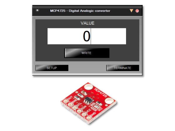
The application is very simple: you can edit the big field to insert a value between 0 and 4095. The, pressing WRITE, you can pilot the device to generate the 0 - 5 volt signal.
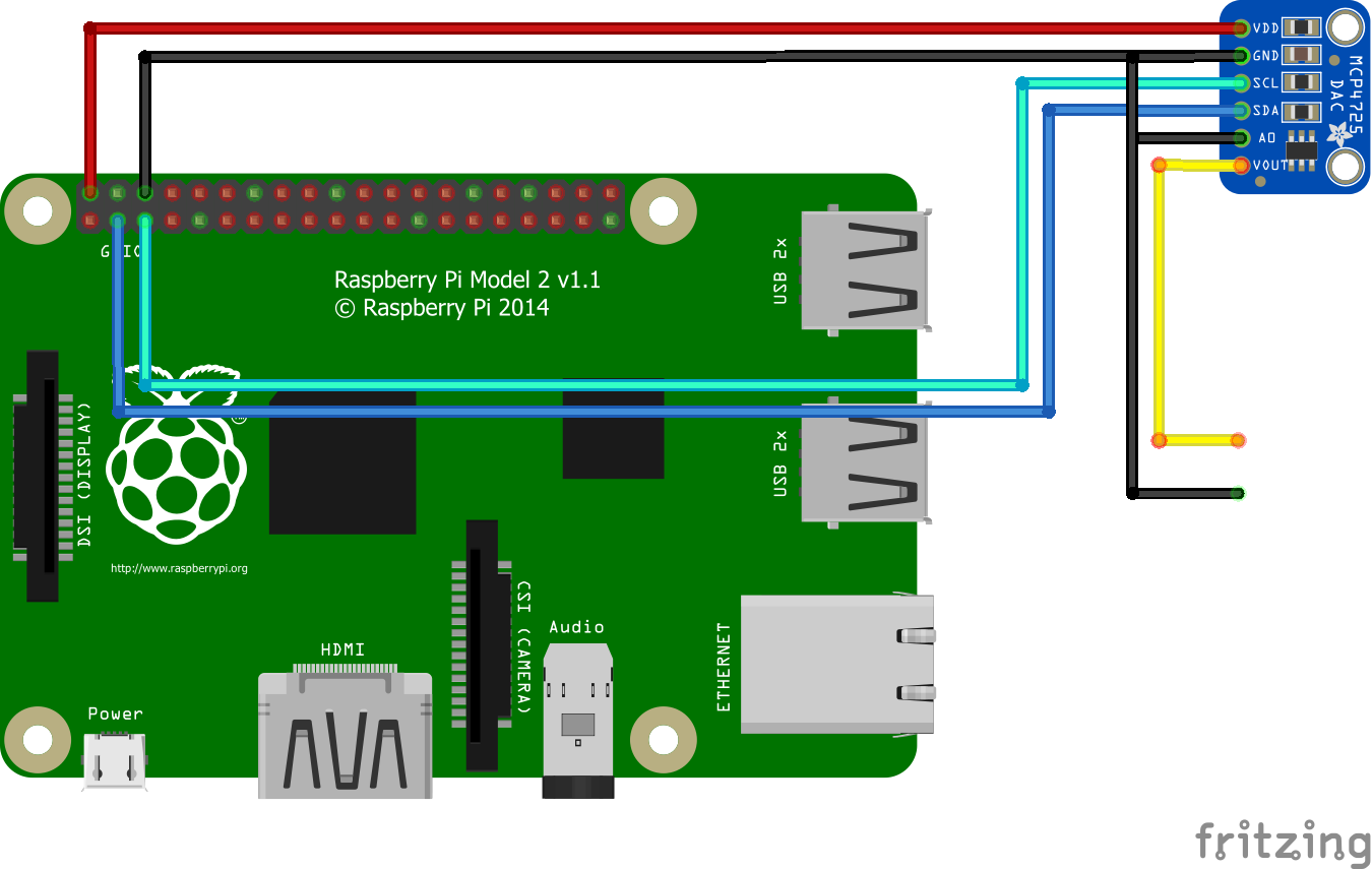
Step 3Looking at the wiring diagram that I posted below, the analog output signal is generated between the yellow connector (positive pole) and the black one (ground) .
At the bottom of the page there are tho buttons: TERMINATE, to stop the app execution, and SETUP to configure it. You can also simply close the interface by pressing the dot in the upper right: in this case the app keeps running on Raspberry.
By pressing SETUP, the setting screen appears, but in this application is an empty placeholder page, maintained for future improvement.
The output is generated.


Comments
Please log in or sign up to comment.