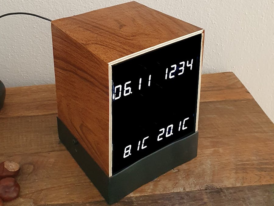
I used to have a cheap and inaccurate clock with temperature display in our living room which I wanted to replace with something with can set the time&date on it's own as you would expect today. Also it should display my available Homematic smart-home data such as temperature sensors and other information (e.g. door bell sensor).
Since there was no such device on the market, I decided to make it myself.
I decided to use the Arduino "Mkr Wifi 1010" for this project mainly for WiFi access capability and available resources. There were a few interesting learnings which I think can be useful for others starting with the same board (see the detailed description below).
Features of my HM Clock Display :
- accurate, self-setting clock (accesses NTP internet time service to set the RTC of the microcontroller)
- receives and displays 2 temperatures (inside and outside) from Homematic (or similar smart-home systems)
- displays time, date and temperatures on bright 7-segment-LED displays
- 7-segment LEDs will be dimmed at night time (programmable)
- an additional 8x8 bicolor dot-matrix display shows status symbols (e.g. WiFi, Temperature or NTP updates etc)
- can display additional information (e.g. I added a visual door-bell triggered from my Homematic door-bell sensor)
- can be controlled via Webpage (access in local WiFi using the IP address or router symbolic name)
- has a backup battery, measures supply voltage and battery level (remaining %) and knows when it's USB-powered
- Arduino MKR Wifi 1010
- 4x Adafruit 4-Digit 7-Segment Display with I2C Backpack - bright White
- 1x Adafruit Bicolor 8x8 LED Square Pixel Matrix with I2C Backpack
- Optional : LiPo Akku with connector JST PHR-2 (3, 7 V; 1200mAh)
Instructions:
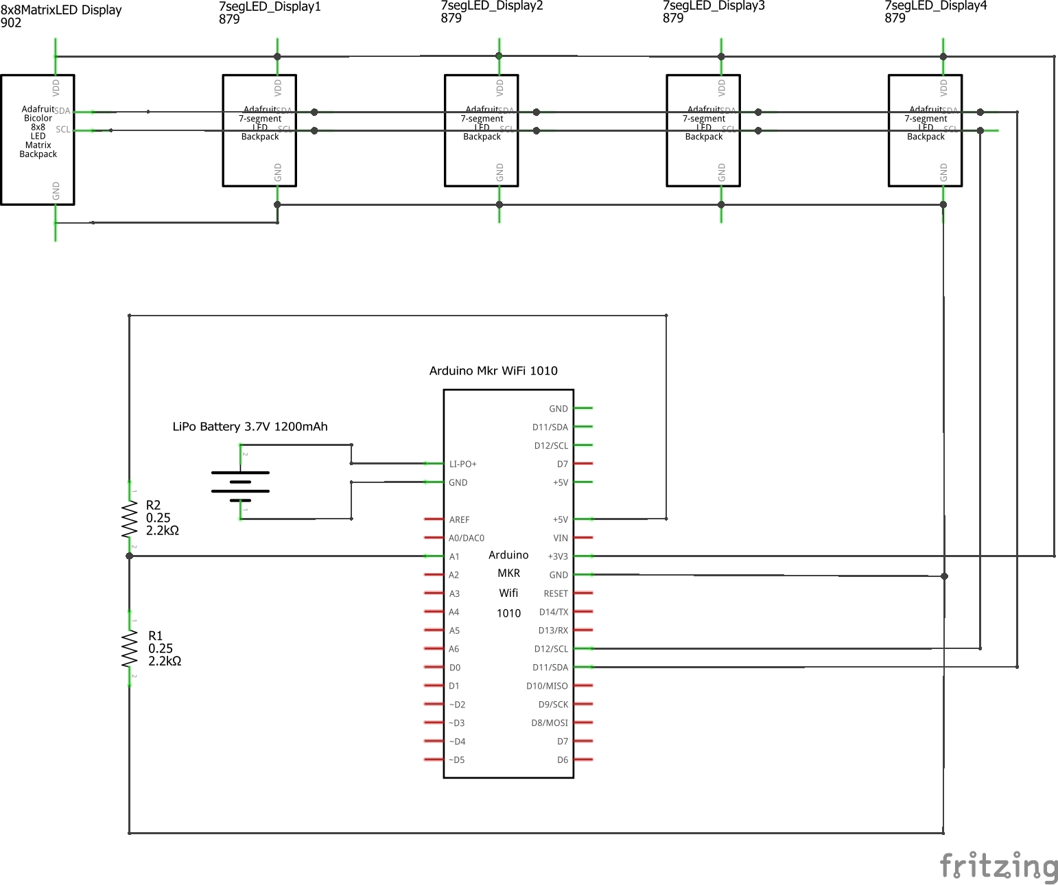
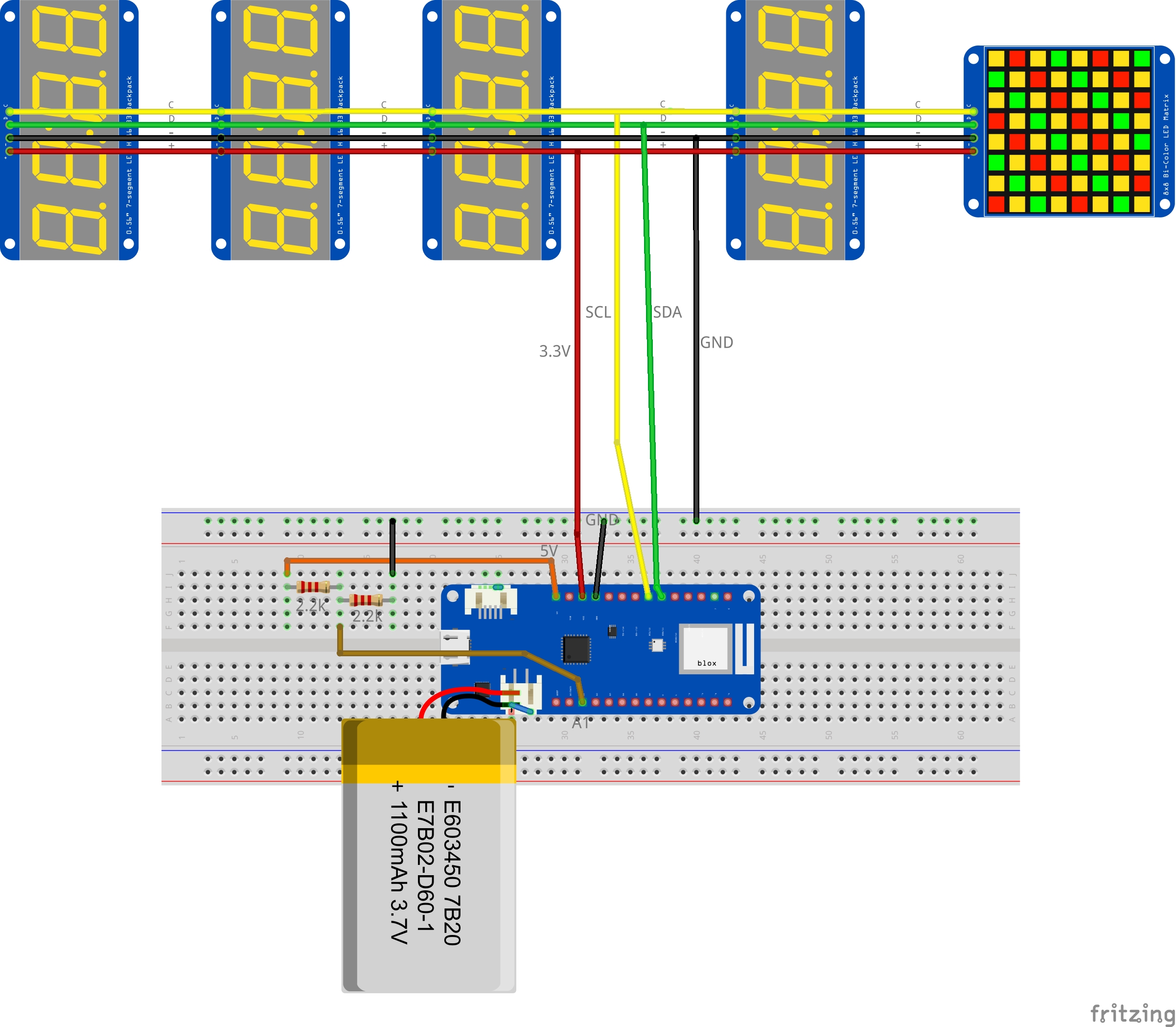
1. To build your own HM display clock, I would recommend to start on a breadboard using the Mkr1010 and the displays connected by patch wires. (The design of the enclosure box is not included here - maybe I will add something later...but then as a 3d printed version).The hardware setup is really easy - see the provided schematics:
- Mount the Mkr1010 Board on a breadboard and connect via (micro)USB-cable to your PC
- Prepare the 5 display modules and connect them all onto the same I2C bus (pins SCL, SDA of the Mkr1010) and power (3.3V and GND).Be sure to have the I2C addresses of each display set correctly to avoid conflicting addresses (see details below)
- Connect 2 equal resistors e.g. 2.2k between "5V pin" and "A1" as well as between "A1" and "GND" as simple voltage divider
- Optionally connect the LiPo battery (3.7V; 1.2Ah typ.) ; make sure the polarity of the connector is correct (details see below) That's it.
2. Prepare your Arduino IDE :2.1 First set the target to "Boards - Arduino SAMD boards - Arduino MKR WiFi 1010" (Maybe you want to try some simple Mkr WiFi 1010 board examples first)
2.2 Then download and install the necessary Adafruit-LEDBackpack libraries for the I2C driven displays (see the good instructions available on Adafruit website: https://learn.adafruit.com/adafruit-led-backpack/downloads)
2.3 Get my Arduino source code (see below), it contains 3 files:
- HMClockDisplay.ino - the main source code
- menu_inline_css7.h - the HTML menu source code (for the website)
- symbols.h - some symbols for the 8x8 dot matrix display
make sure they are all in one folder
2.4 Change your personal settings in the "USER settings" section at the beginning of the source code: Enter your home WiFi network SSID(name) and password and adjust your Timezone and Daylight Saving Time(DST) as needed :
// USER settings :// WIFI Settingschar ssid[] = "XXX"; // your WiFi network namechar pass[] = "YYY"; // your WiFi password// Timezone Settingsint GMT = 1; // adapt to your time zone (e.g. Germany is GMT+1 -> set to 1 )int DST = 0; // adjust daylight saving time (default = 0 : no DST (Wintertime)
Note: for inital testing, I would recommend to use your "normal" local WiFi access (no major restrictions like in guest WLANs) to avoid any issues.
2.5. Compile and upload the code to the Arduino board
Use the serial monitor to get detailed information from the device for initial testing. There will be many log outputs which can be helpful to understand any issues like WiFi connection problems etc.
Detailed description:1. WiFi NINAThe Mkr Wifi 1010 board is based on the microcontroller SAMD21 connected to a module from u-blox, the NINA-W10, a low power chipset operating in the 2.4GHz WiFi range. To access to your local WiFi network, the provided WiFiNINA library provides all required functions. There are plenty of examples and existing projects using the WiFiNina. See the available documentation on : https://www.arduino.cc/en/Reference/WiFiNINA
In my project, I used WiFi network-access to :
- access the internet time protocol NTP to set the real-time clock periodically
- provide a simple webpage for configuration (basically it acts as a little server)
- receive data from my Homematic smart home system to be displayed (temperatures etc)
Notes:
- You may need to update the Nina firmware after the intial setup of the Mkr1010 board in your Arduino IDE. The version can be checked and updated in the Arudino IDE. This update process is described in the WiFiNINA webpage mentioned above.
- To access the device from your local WiFi network easily, configure your network router to always use the same IP address for it. Most routers also let you assign a device name (so you don't need to type in an IP address to your browser). I used "HMDisplayClock" which lets me access the control page in any browser within my WiFi network by simply typing in http://HMDisplayClock(alternatively, using the IP address of the Arduino Mkr 1010 board of course also works...)
- If you want to program your own WiFi connected device which needs to be accessable all the time, here is a tip : make sure to check regulary if you are still connected or not. Your router will disconnect devices from the network from time to time... so if you would establish WiFi only once (in the setup routine), you will lose the connection after a few hours. In my case I am checking the connection each second in the "handleWifiClient" subroutine.
The Arduino will get the exact time from the Network Time Protocol (NTP) service which returns the "epoch time". The returned "epoch timestamp" is the number of seconds that have elapsed since January 1, 1970. So it is necessary to convert the time stamp to a human-readable date and time information. In addition, timezone and daylight saving time corrections has to be made. The subroutine to adjust the time zone is based on the excellent work "It's about time" from Doug Domke (thanks for sharing !) : https://www.hackster.io/doug-domke/self-setting-super-accurate-clocks-5f1162
For this, Doug's routine fixTimeZone() was a great help since adjusting the time zone can be rather complicated. The build-in real-time-clock of the microcontroller (SAMD21) will be set periodically using this information (I do the update each hour). Once a successful NTP update was received, a green "NTP" symbol lights up for a few seconds on the matrix display :
To visualize all information, I have decided to use large and bright LED displays. They can be mounted behind a smoke glass cover and allow a nice design of the clock module. In addition I am using a bicolor 8x8 matrix module for occational status information.
All display modules are made by Adafruit, are well documented and come with software libraries. The displays are controlled by I2C (all are connected on the same bus) and can be powered by 3.3V.(Note the Mkr1010 is a 3.3V device, so don't mix with 5V parts !).
- I2C Addressing :Using several modules, the I2C addresses of each display module needs to be set to avoid conflicting addresses. There are 3 "address adjust soldering jumpers" available on each display. Make sure you set a different address for each module.See the Adafruit page for more details : https://learn.adafruit.com/adafruit-led-backpack/changing-i2c-addressIn my case I have chosen the following addresses (see setup routine): Time Display Module : 0x70 Date Display Module : 0x71 Temp1 Display Module : 0x73 Temp2 Display Module : 0x74 Matrix Display Module : 0x72
- Power budget check: All displays are connected to the MKR1010 Board VCC pin, which is a regulated 3.3V output. The specification for the MKR ZERO tells that it can supply up to 600 mA. That is the same for the MKR WiFi 1010, because it uses the same voltage regulator (AP2112K-3.3). My measurements have shown all 4 displays supplied by 3.3V draw not much more then 120mA in total, so it should be ok.
To visualize information such as temperature values from the Homematic smart-home system, the central unit (CCUx) needs to provide the sensor data to the clock by local WiFi connection. For this, the CCU accesses the webpage of the clock with a parameter...like this : "http://HMDisplayClock/?tempR=20.5"
With your own version of the clock, try entering this in your browser manually first... if everything works, it will update the right temperature display to 20.5C as shown below :
Then follow these steps to enable sending data from your Homematic Central Control Unit (CCUx) to the clock automatically:
4.1.Install the following two Addons in your Homematic CCU :
a) XML-API : provides xml request functionality as an interface to available HM devices (e.g. sensors) https://github.com/homematic-community/XML-API
b) CUxD Deamon : To send data with the script-command CMD_EXEC to the Clock using WiFi access https://www.homematic-inside.de/go/cuxd
To enable the CMD_EXEC function for the first time after installing CUxD, enter settings and create a new device of type "(28) System" with the function "Exec" in the CUx daemon then confirm the new device via your CCU inbox and restart your CCU (instructions for this step are here (in German) : https://homematic.simdorn.net/cuxd-installation/)
4.2. To select specific homematic sensor names (datapoints) which should be displayed on the HM Display Clock, follow these steps : open the XML-API menu :
Settings-> Control Panel -> Additional Software-> XML-API Settings -> statelist
... all actuators will be listed...
locate the right <datapoint> and copy the exact name to a texteditor
e.g. "HmIP-RF.000ED8A9909BB2:1.ACTUAL_TEMPERATURE"
4.3. Create a simple CCU program for sending the data periodically. In my case I wanted my indoor and outdoor temperature sensors to be send to the clock automatically each 10min.
For this, I created a time controlled sequence as CCU program like shown above. This CCU program will be executed each 10min and then calls a script like this :
string Temp1 = dom.GetObject("BidCos-RF.OEQ0670990:1.TEMPERATURE").Value().ToString(2);string Temp2 = dom.GetObject("HmIP-RF.000ED8A9909BB2:1.ACTUAL_TEMPERATURE").Value().ToString(2);string url = "http://HMDisplayClock/?tempL="#Temp1;dom.GetObject("CUxD.CUX2801001:1.CMD_EXEC").State("wget -q -O - "#url);string url = "http://HMDisplayClock/?tempR="#Temp2;dom.GetObject("CUxD.CUX2801001:1.CMD_EXEC").State("wget -q -O - "#url);
replace the sensor objects above in line 1+2 with your datapoints of choice (see step 4.2)
(perhaps also useful for you : I used this useful tutorial to enhance my own knowledge on this topic (in German): https://www.verdrahtet.info/2019/01/04/homematic-statusanzeige-selbst-genaut/)
The above method can be extended further of course. In my case I also used it to show a door-bell symbol each time my homematic door-bell sensor has been activated.
Finally - just for completeness - instead of Homematic you can of course use any other local service to provide data, as long as you can send out the information in the above described http access format.
5. Battery (optional)You can use a Li-Po rechargable battery to keep your clock running after deconnecting USB power as an option. The Arduino Mkr WiFi 1010 board has a built-in charger Li-Po charging circuit (BQ24195) which allows the Arduino MKR WiFi 1010 to run on battery power or an external 5 volt source, charging the Li-Po battery while running on external power.
To detect USB-Power(+Charging) or battery mode in the application, measuring the "5V" output pin of the Mkr1010 board is a suitable method :If the measured voltage on 5V-pin is around 5V, then USB-power is connected, if on battery it's 3.3V.Use a 2:1 voltage divider (2xR) from 5V pin to A1 and GND to monitor the voltage level (since no 5V can be supplied to 3.3V ADC-Inputs !).See the schematics for details.
To measure the battery voltage itself, use the supplied input signal available on Mkr1010 board by "sensorValue = analogRead(ADC_BATTERY);"
The voltage (3.3-4.2V) is a good indicator for the remaining capacity. I am evaluating 5 different levels (see the source code).
Notes :
- use Li-Po rechargable single cell battery, 3.7V, at around 1024mAh is recommended by Arduino
- The connector type for the battery is JST PHR-2 (on Arduino side it's JST S2B-PH-SM4-TB). IMPORTANT : Check the polarity for the JST PHR-2 connector !With the USB connector of the board on your left, + should be the left pin (oriented towards the USB connector), see the image below.Some available LiPo batteries have reversed polarity ! Luckily it's easy to change the connector polarity if needed.
- Important note on switching power sources - this is not well documented : According to Arduino, switching from one power source to the other should be done automatically.BUT : If the MKR Wifi 1010 is running on Li-Po battery and then USB is plugged in to charge, it will be dramatically current limited !As a consequence, the CRG LED will blink after a while and the board will power off due to insufficient power. This is due to the following limitation:Since the USB monitoring function (D+ and D-) of the TI BQ chip is not implemented, it is unable to tell what kind of power source it is.As a result, the BQ24195L writes a safe value of 0x30 into reg 0x00 which limits input power to 100mA. Charging then enters DPM mode and the charging voltage drops on the battery to limit the current. (source : https://forum.arduino.cc/t/mkr-wifi-1010-battery-circuit-operation/565243/46)The solution : A RESET is needed if switched from battery back to USB-power to return to the default settings.In my case, I am using the watchdog reset (see source code).There are surely more elegant ways to solve this issue (e.g. re-configuring the BQ24195), but for me this was sufficient.
That's it. I hope you enjoyed the project.
Cheers
Mac


Comments
Please log in or sign up to comment.