


Hardware components | ||||||
| × | 8 | ||||
| × | 13 | ||||
| × | 1 | ||||
| × | 1 | ||||
| × | 1 | ||||
| × | 1 | ||||
Hand tools and fabrication machines | ||||||
 |
| |||||
 |
| |||||
 |
| |||||
 |
| |||||
 |
| |||||
Interconnects are a weak point in the Arduino universe. The DuPont connectors allow easy connection, but a single lead has little retention. This makes building permanent projects a problem. Although there are lots of terminal shields with power pins, the power pins are either separate from the signal pins or they not in the same order as the device needs. This makes power connections problematic.
Solution:Having tried several different shields for the UNO and Mega 2560 I finally found a terminal shield that brought out EVERY pin to a screw terminal. Perfect for connecting the signal leads. But every device needs power or ground or both and the CPU boards are power consumers, not power sources. So an easy connection with screw terminals for power is called for. This card attaches directly to the Mega 2560 or UNO terminal shield and provides power input and distribution for a dozen assorted devices, plus a couple of free ground pins. It can also be mounted separately using the four corner mounting holes.
The parts needed are commonly available and construction is easy but does involve soldering.
Start with a Dreyer Electronics DE0708V 2-1/4 x 3-1/2 strip board. These are nice heavy weight substrate with double sided connection strips with plated thru holes.
Drill a #4 thru hole (1/8") at column 4, 12th row up, and then a second hole 11 columns to the right. These holes should line up EXACTLY with the mounting holes on an UNO or Mega 2560. Even if a different screw terminal board is used, these mounting holes should still work.
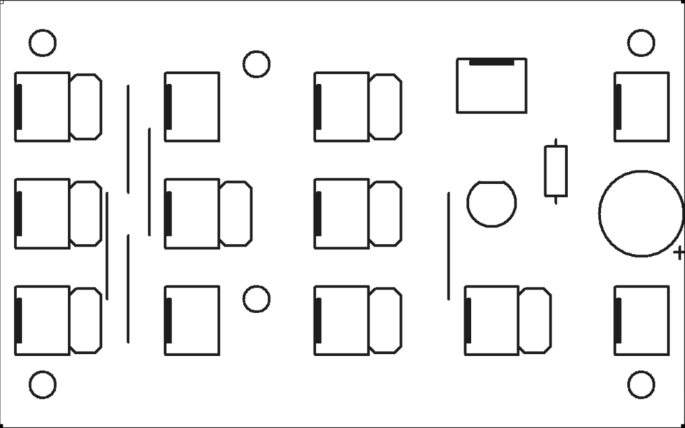
The location of the terminal blocks and associated wiring have been selected to not land on the pass thru connectors on the screw terminal shield.
We're using individual two position, .1" spacing, terminal blocks from Pololu. I chose individual stations instead of long strips to make it more obvious that a power pair from a device are connected adjacently and individually.
Use a piece of stiff card to form a sandwich, trapping the terminal in place as you flip it over from positioning to soldering. This saves a huge amount of frustration.
Solder one leg on each terminal block, then inspect to make sure that it is fully flat to the surface of the strip board. Reheat while pressing to square up the terminal.
The layout is more complex that it looks. The terminals are positioned so that nothing is directly over the pass thru connectors of the terminal shield. The 3D printed spacers are the same height as the standard connectors. The mounting holes are for #4 hardware and are directly in line with the hole on the terminal shield.
Once the terminals have all been soldered and inspected, it's time to add some bypass caps. These.1 uF ceramics are located behind every possible terminal block to prevent switching noise from spreading on the card itself. I plan is to add a 470uF cap for the board as a whole, but they're on backorder at the time of this writing.
The legs of the caps are spread to hold them in place as they're inserted directly behind each terminal block. The ground pair block and the two blocks at the edges don't get caps due to layout constraints.
All the caps are installed, soldered and trimmed. I normally trim twice. Once to get the long ends out of the way and then a second, final trim to get the leads as flush as possible without damage. This makes handling the board easier on your fingers and insures no missed "wild hairs" causing issues.
Secondary Fab:After the caps are all soldered, the LED and it's series resistor are added. The LED can be whatever you have kicking around, I use RGB color changers 'cause they look cooler than just an steady on LED. Adjust the resistor value for ~20mA (50 ohms/volt for drop voltage). The RGB LED I'm using has a Blue LED forward voltage of ~2.5V on a 5V power supply. This means I need to drop ~2.5V and at 50 ohms/volt the suggested series resistor is 250 ohms. Since I had a bag of 270 ohm resistors, that's the value used.
The black cast to the LED is due to a dab of paint applied at incoming QA. Since all the LED's we buy tend to have clear bodies, there is no easy way to tell them apart if they get mixed. We add a dab of appropriately colored paint on the bases, this allows us to identify the LED without powering it up and (usually) enhances the color. For RGB we needed a unique color not found in any other LED - black. And so that is the source of the black cast. In operation it gives the LED a black background and it looks that much brighter in comparison.
The connection between the series limiting resistor and the LED is thru an otherwise unused runner. The cathode side of the LED connects directly to a ground trace and the resistor to a power trace.
Final Wiring:The next step is to add a set of six jumper wires to connect each group of terminals together. Since the top side of the strip board is plated, insulated wires must be used. Three red and three green wires are needed. The 20 ga hookup wire insulation can be slipped along the wire. Strip at least 4" of insulation off hookup wire and then slip three short pieces of insulation along. The insulation should be two with.5" and one with.6". You can easily eyeball this by using the strip board traces as a counter. Measure two pieces with five hole spacing, and one with six. These wires are installed as shown and soldered in place.
The entire board is rung out with a continuity tester to verify that the top of every terminal is connected to the appropriate buss and that there are no shorts. This is a critical step to insure that nothing attached gets fried. The terminals are color marked with a Sharpie, again to prevent accidental miswiring.
Final Assembly:Because of the small size of the terminals, they're not physically strong. To beef them up a bit I add a dab of gel 5 minute superglue to either side of the terminal block at the base.
Tip: Back the screws of the terminals out so make it easier to insert. The DD) and D1 as well as other "unused" pins are the only ones initially screwed down. This allows you to more easily count and identified used vs unused pin stations.
The completed board is mounted with a pair of 4-40 x 3/4 allen cap head machine screws and Nyloc nuts. Fiber washers are used under the head of the screws and under the nuts to prevent shorting. 3D printed spacers are used to keep pressure off the connectors and to keep the boards from flexing.
The completed "sandwich" is built from the bottom up with:
- 3D printed base plate
- MEGA 2560 attached to base plate with two 4-40 x 1/4 screws
- Mega Terminal Shield is held in place by pin friction
- Power Distribution Board mounts to terminal shield with mre 4-40 hardware and 3D printed spacers.
The stack splits apart without tools and separates the MEGA and base from the screw shield and PDB. However the whole stack can be mounted as a unit as the extra wide base allows mounting with the terminal shield in place.
The two base plate mounting holes are tapped 4-40 thru. 3D .STL file for this base is attached.
Cable Development:Connecting the individual IO devices to the screw terminal shield requires creation of a dozen or so assorted cables. The far end of the cables is pretty much universally female (sockets). The near ends are stripped, twisted, tinned, and then inserted into the appropriate terminal location and screwed down. This gives the solid, vibration/pulling proof, connection required for reliable long term operation of a saleable product.
I start with 30cm/12" DuPont M-F ribbons. (The M-F are more versatile than the M-M or F-F ones as they can be used for wiring either end or used as extensions.)
The duPont ribbon cables are stripped off in groups approriate for each device. If possible, each four or more wide ribbons, should start with a brown wire as pin #1 and going red/orn/yel etc. from there. The black and white wire pairs are useful for switches, speakers, etc., that only need two wires. Yes, you wind up with a lot of "middle colors" left over, but the color consistency not only eases assembly and troubleshooting, but it looks professional too.
A 3D printed shroud is placed on the socket end of the ribbon cable once the M ends have been removed. (If you're making a extension cable, a split shroud is used on both the M and F ends.)
An identifying label is placed on each shroud so that when correctly mated, both labels are visible. At the device end, the labels are oriented to be readable when installed correctly. If you can't see the label, the connector is flipped.
The shoud also greatly simplifies mating multiple DuPonts, versus trying to mate four or more loose pins. The shroud also increases retention force as all the pins must separate at once instead of individually.
Each device usually requires both Vcc and Gnd connections. Use various sizes of HS tubing to break out and group the ribbon ends. The Vcc and Gnd wires are broken out and bound at the split with a piece of 1/8" HS tubing. Then the two power wires are stripped apart and a piece of 1/16" HS tubing placed over the GND lead. This is important because the color code on the ribbon does NOT follow any polarity convention. Brown and red are just as often Vcc and Gnd as they are Gnd and Vcc! The piece of HS identifys the NEGATIVE lead no matter the color of the wire.
A 3rd, larger piece of HS is placed over the cable as a whole. This piece is shrunk last, to take the slack out of the remaining cable after wiring is complete.
The ends of the ribbon are separated, stripped, twisted and tinned. Then they're trimmed to ~3/16" (4-5mm) for insertion into the terminal blocks.
After all cables have been connected and tightened, go back and retighten EVERY used screw terminal. Most of the time they're snug, but with a large number of screw terminals there are always a couple that need extra snugging and, very occassionally, the one that was never tightened at all.
Attach the cables without the far end devices initially. Once all the cables have been attached, bundle by destination (front, read, side, etc.) and finally connect the modules.
Conclusion:I hope this helps suggest solutions to YOUR Arduino power issues.
I have been building a series of weather station/clocks that use a dozen assorted devices. Using the completed "sandwich" as a starting point, I was able to completely all of the devices and have them connected **ROBUSTLY**, immune to shaking, tugging and the rigors of shipping in just a couple of hours with standard modules.
I wired it with ease and simply tinned the ends of the duPonts. It might be possible to use the tips of the DuPonts in the terminal blocks, but it doesn't seem like a good idea for some reason that I can't articulate. But even stripping and tinning the individual leads didn't really take that much time and each connection is very secure. Once all the connectors were attached the unit can be mounted as a single assembly and then the modules plugged in. The one I build today came up and ran on the first try.
Update June 25th:Built a couple more with some slight changes. Larger terminals, a filter cap, better layout, etc.
Here you can see the board undergoing hot test with a 55VDC power supply. The LED and cap work together. The cap is discharged by the LED, which stays lit momentarily, showing that the cap is OK.
I've got enough parts to make one more board. Two will be retrofitted into existing units while the last two will go into new units.
The 470uF caps finally arrived and provide a little extra current reserve in addition to the .1uf bypass caps. The larger .2" terminal blocks mount better (no glue needed) and accept bigger wires than the smaller terminal. Looks better too. The mounting holes on the left unit has yet to be drilled.
The 470uF cap value was chosen, not for its specific value, but because the lead spacing was .2".
I think the big 10mm LED is a little over the top. The T1-3/4 LED mounts better too.
The design is converging quickly. With any luck, (and KiCAD), I should be able to make a PCB for the final iteration.
PPS:Been tinkering with my laser engraver. I cloned my little dev board in some free PCB design software and isolated the silkscreen layer. Press <PrtSc> and a minute with paint.net and I've got the image scaled 1:1 at 300 DPI. I don't have a registration jig set up so my first attempt is skewed slightly, but things still line up well enough for a small shop's output. Whadda'ya tink?
I'm thinking of kitting up all the parts and selling it or, for slightly more, selling it as a ready to install unit.
BOM:- 3.2" x 2" .1 grid single sided strip board -- 1 - Jameco Part no.: 2191488
- .2" dual screw terminal block -- 13 - Jameco Part no.: 2120647
- .1 uF, 16v, .1 spacing ceramic bypass cap -- 8 - Jameco Part no.: 151116
- 470 uF, 25V .2 spacing 'lytic cap -- 1 - Jameco Part no.: 158289
- 270 ohm, 1/4w resistor -- 1 - Jameco Part no.: 690726
- RGB LED Auto Slow Fade Water Clear T1-3/4 -- 1 - Jameco Part no.: 2299471
- Wire, hookup, 22 ga., red, .5" insulation -- 2 - Jameco Part no.: 36856
- Wire, hookup, 22 ga., black, .5" insulation -- 3 - Jameco Part no.: 36792
Grand total: Under $13 as of 25Jun22


Comments
Please log in or sign up to comment.