madmark2150
Published © GPL3+

Rick & Morty Steampunk Multifunction gadget

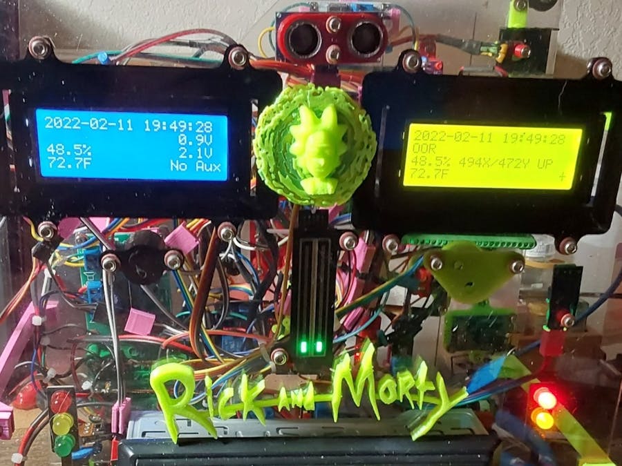
Weather station with remote outdoor sense, FM radio, blinkey lights and secret hidden compartment., Magic 8-Ball, Insulin Estimator, etc.

AdvancedWork in progress715
Rick & Morty Steampunk Multifunction gadget

Things used in this project

Hardware components

Arduino Mega 2560
Arduino Mega 2560
×1
DHT11 Temperature & Humidity Sensor (4 pins)
×1
Ultrasonic Sensor - HC-SR04 (Generic)
×1
Linear Regulator (7805)
×1
WPM402 LM2577 DC-DC VOLTAGE STEP-UP (BOOST) MODULE
×1
WSAH190 2x5W amplifier for MP3 player
×1
Prototype Screw/Terminal Block Shield Board Kits Set For Arduino MEGA-2560
×1
5V 4 Channel Relay Board Module Optocoupler LED
×1
12 Level Stereo LED Indicator VU Meter
×1
RTC DS1302 Real Time Clock Module
×1
5V Mini Traffic Light Red Yellow Green 5mm LED Display Module
×2
Dual Electronics XDM17BT Single DIN Car Stereo , Bluetooth, Siri/Google Assistant , USB, MP3, AM/FM Radio
×1
28BYJ-48 5V Stepper Motor, 5 wire
×1
KY-023 Joystick mounting box
×1

Software apps and online services

Arduino IDE
Arduino IDE
Tinkercad
Autodesk Tinkercad
NanoCAD

Hand tools and fabrication machines

Grizzly G0923 3D Printer
DISCONTINUED JAN22

Story

Read more

Custom parts and enclosures

3D .STL print file - Mounting base for Arduino Mega 2560

Panel mount for Arduino Uno and Mega 2650. Mount engages all six mounting points. Five with meltable alignment posts and one ready to be tapped 4-40 for a retention screw. Wide panel mounting tabs extend past screw shield for easy mounting without disassembly. Four side tabs with #6 thru holes for panel mounting. Design is filleted for strength. Height is 1/4" to bottom of Uno/Mega. Suggest #4 fiber washer under screw head to prevent damage to Uno/Mega.
90% infill needed for strength. 4.12m of 1.75mm PLA @ 210C & 35mm/s, .4mm nozzle, ~1 hr print time, ~90mm x 100mm x 11mm

3D .STL print file - Connector Holder for Dupont connections

Arduino comes with lots of Dupont wires. After use, the connector retention may leave a bit to be desired, especially for long term connection reliability. To solve this problem, here is a little piece that engages the wires on either side of the connection, taking all of the strain off the connection to prevent pull-apart.
Print at 90% infill for strength.

ZIP with Multiple 3D .STL print files - Connector Shrouds for Dupont connections

Single Dupont connectors are difficult to install onto multi-pin connectors. Additionally, single pins don't grip well. Groups of pins, however, are easier to insert and harder to mix up as a unit. These shrouds group sets of 2, 3, 4, 5, 6, & 8 stations into one connector body.
Print at 90% infill for strength. Print times 3-15 min.

3D .STL print file - Vcc & Gnd buss bars for 12 ga wire.

Wiring lots of devices to Arduino is often difficult because there never seem to be enough power and ground connections. The pin boards just don't hold well enough for reliable module powering. Solve the lack of power and ground pins by adding 12 ga solid copper wire buss bars. Strip a few inches of 12-2 wire and use the ground wire for the busses.
Solder your individual sensor wires to the busses for reliable power connections. Power with any +5V or +3.3V power source.
Two #6 mounting holes provided. Buss voltage (Vcc/Gnd) is integral to the design. Support posts are filleted for strength.
Print at 90% infill for strength.

3D .STL print file - SDA/SCL Buss bars for 12 ga wire.

Want multiple I2C devices but don't have connections? Add a 12 ga buss bar for each signal SDA and SCL. Signal name embossed in base. Support towers are filleted for strength. Use 12 ga solid copper wire as buss bars. Strip a short length of 12-2 house wire and used bare ground as buss.
Print at 90% infill for strength.

3D .STL print file - Box with 1/4" hole for toggle switch, screw lid

Need to mount a switch to control power to your project. Add any 1/4" dia switch in the built in hole. Use a soldering iron to melt cable entry notch to match your specific needs. Four corner posts designed to be threaded 6-32 x 1/2". Corners internally filleted for strength.
Print at 90% infill for strength.

3D .STL print file - LCD2004 Real Panel Mount 3D print file

Rear panel mount for LCD2004 type displays. Provides four #6 mounting holes to panel. Two 4-40 tappable studs for LCD attachments. Allows I2C four wire interface card.

3D .STL print file - HC-SR04 Sonar Rangefinder Rear Panel Mount

This is a panel mount for the HC-SR04 ultrasonic rangefinder module commonly found in Arduino kits. The mount has two #4 thru holes for attachment to the panel. The HC-SR04 module firmly slips into place and a drop of superglue can be used for a permanent grip if so desired.
Use 90% infill for strength when printing.

3D .STL print file - 5/16" potentiometer 8-way chassis mount

This file prints a mounting bracket for a standard 5/16" diameter mini potentiometer with anti-rotation tab. The pot can be mounted on either side in any of four orientations allowing complete flexibility in mounting. The base of the bracket has two #6 thru holes for mounting. The base and bracket are filleted for strength.
Print at 90% infill for strength.

3D .STL print file - ULN2003 Stepper Motor Driver Board Mount for 28BYJ-48

Mount your stepper driver card with this simple 3D print., Mount has two holes for card and two location posts. Mounts to panel with to #6 thru holes. Print at 90% infill for strength.

3D .STL Print File - Joystick Box for Arduino Analog Joystick w/pushbutton action

The X-Y analog joystick has a push button for Z. The Arduino module has four #4 thru holes on a .80" x 1.05" grid. This box has a spherical opening that exactly fits the joystick. A cutout is provided in the side for cable egress. The four joystick mounting holes need to be tapped 4-40 prior to use. The four cover screw holes will accept a 6-32 x 1/2" screw without threading - do not over torque.
The corners are rounded for comfort. For correct X-Y orientation the cable exits left.

3D .STL print file - LED diffuser for Stepper Motor Driver

The stepper motor driver card has four VERY BRIGHT LEDs that indicate the state of the four drive lines. In this project the LEDs are visible and too bright. I printed this diffuser to tone down the LEDs without obscuring their function.

3D .STL print file - Traffic Light Housing for LED indicator

Decorative piece that looks like a traffic light. Slips over three LED indicator.

Schematics

IO Device List

Too many IO's to build out one large schematic. Use the following table to map devices. Individual sections will be drawn and added as they are finalized.

IO Map

All IO's and their assignments. Device list and IO map together define MEGA 2560 connections.

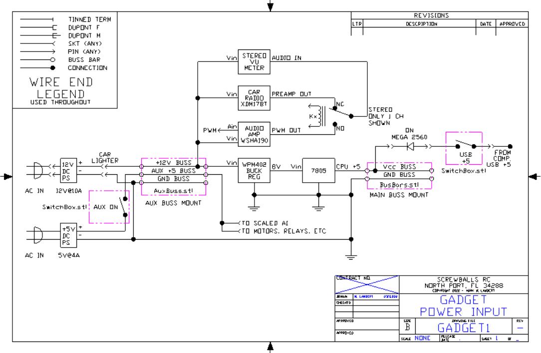
Gadget Project - Power Supplies

Shows power section including main +12 and +5 development as well as aux +5 and related items.

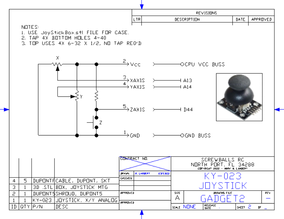
KY-023 Joystick

Joystick Schematic & Connections

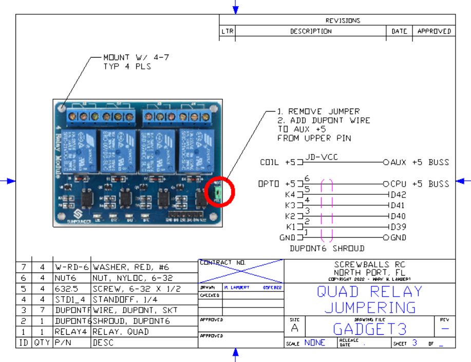
Quad Relay Jumpering

Modified item drawing showing auxiliary power connection and mounting kit for installation

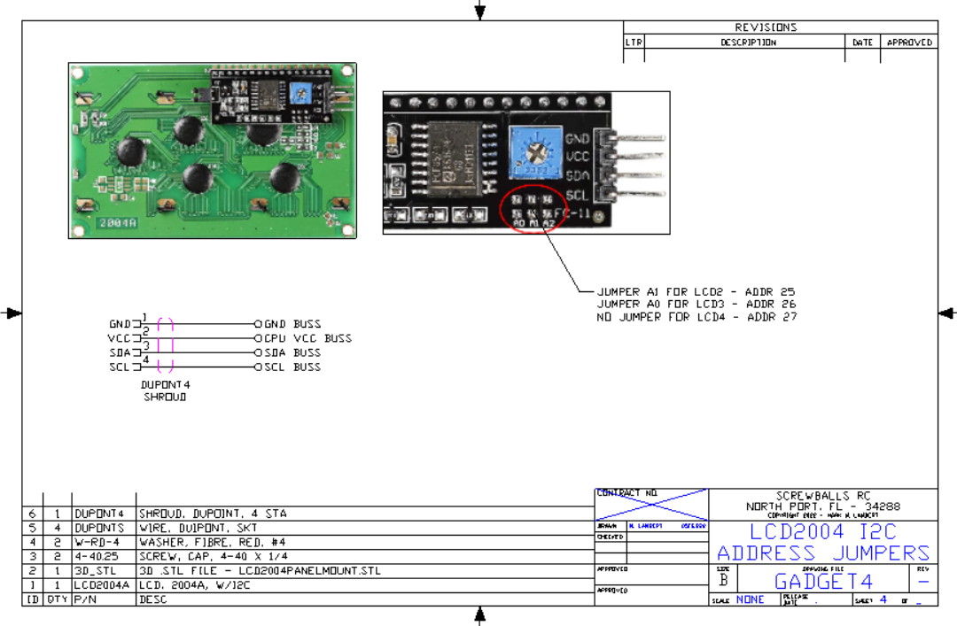
LCD2004 I2C Address Jumpers

Modified item drawing showing address jumpers and cable with mounting for LCD2004 display with I2C daughter card.

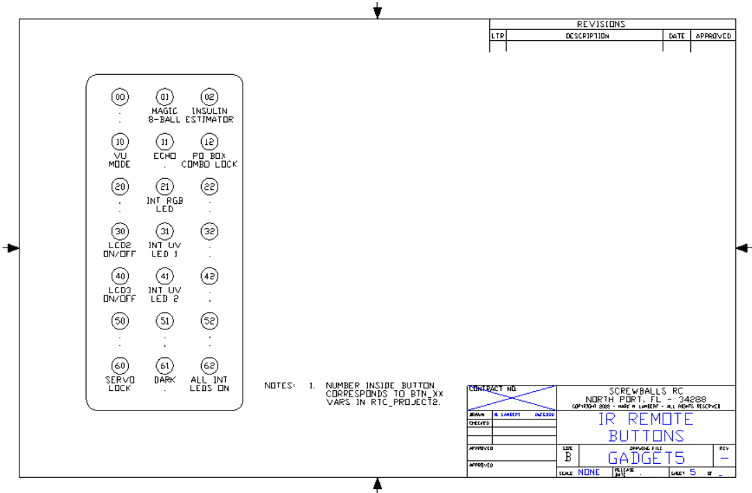
IR Remote Buttons

Button assignments to IR remote control mapping button ID's to BTN_xx definitions in the code. Drives master SWITCH / CASE statement block.

Code

Rick Gadget Box - V5.09 with remote control, magic 8 BALL, & insulin calulator, PO Box Sim

Arduino
Fully loaded Mega 2560 Steampunk Rick & Morty Gadget Box. Does bunches of stuff
Time/Date
Dual 20 x 4 LCD displays, one blue/white, the other yellow/dark
Temp/Humidity
Joystick State
Light/Dark LDR with relay
Remote IR operation
PO Box Combo Lock with servo control
Stepper Motor Control
Insulin Estimator
Biker Magic 8-ball swami
Rangefinder
Noise generator
Radio
VU Meter
Blinkey light thing-y

If you need RUNNING sample code for most common devices, it's here.
//
// Rick Box time/Temp display baseline - Mark M. Lambert - December 6, 2021
//
// This is an attempt to fully load an Arduino Mega 2560 controller.
// We're real close to 100% utilization with everything but the kitchen 
// sink installed (it's on back order ...)
//
// This is a steampunk, over the top, 3d printed, lexan and wood remote control
// gadget that does lots of things with blinkey lights, remote control and it
// even plays music.
//
// It also acts as biker magic 8-ball and an insulin computer. It reads analogs for
// the blood sugar number & joystick, turns lights off at dark, knows what time it is,
// can communicate remotely, switch meter feeds, control blinkey lights, measure
// distance, and move steppers and servos - all at once!
//
// We're down to the last 5 D's, but we still have 8 AI's
//
const float Version = 5.09;
//
// V5.09 - 11Feb22 - MML - Add insulin estimator & PO Box sim using pot as input device
// V5.08 - 08Feb22 - MML - Clean up LCD layout
// V5.07 - 07Feb22 - MML - Make 9-ball biker & get VU meter wired
// V5.06 - 06Feb22 - MML - Add Magic 8-ball
// V5.05 - 05Feb22 - MML - Get 2nd servo running - All remote buttons working, codes verified
// V5.04 - 31Jan22 - MML - Stepper fixed - odd phase ordering and setting RPM fixed it
// V5.03 - 30Jan22 - MML - Servo working, still wirinjg, diddle with stepper
// V5.02 - 27Jan22 - MML - (Cont.) - Lots working - Echo & clock up, 
// V5.01 - 26Jan22 - MML - (Cont.)
// V5.00 - 24Jan22 - MML - Upgrade IO's (again)
// V4.03 - 12Jan22 - MML - Test IR remote
// V4.02 - 11Jan22 - MML - Work on Touch sw & knock
// V4.01 - 10Jan22 - MML - Try to get hardware to run - everything lights up
// V4.00 - 08Jan22 - MML - Align I/O's with "as built" hardware
// V3.01 - 16Dec21 - MML - Get RTC and rangerfinder working
// V3.00 - 14Dec21 - MML - Get 2nd lcd working
// V2.00 - 13Dec21 - MML - Strip down to get clean compile
// V1.01 - 10Dec21 - MML - Continue baseline
// V1.00 - 06Dec21 - MML - Baseline with LCD - Mega 2650 has built in pullups
//
// ----------------------------------------------------------------------------
// ----------------------------------------------------------------------------
//
// Device Master List
//
// Mega 2560          Processor
// +12 to +5 Vreg & Buss Bars
// I2C devices
// 1602 LCD           Command display
// 2004 LCD #1        Indoor Display
// 2004 LCD #2        Outdoor Display
// BHT280 Baro        Barometric sensor
//
// Echo Rangefinder
// Traffic Light
// FM Radio (Button)  <<====== OUT - Real Radio in
//    Analog VU meter Subsystem
// IR remote command in
// LDR light sensor
// Analog Joystick with push sw
//
// K1-4, 5, & 6 relays
// RTC
// DHT11 Temp/Humidity (Indoor)
// ESP-01 WiFi - From Outdoor DHT-11
// Touch Sensor
// Servo output - Haven't added IO's yet or quite figured out what this will do. 
//    I'm leaning to a secret compartment with a hidden release and maybe the knock sensor
// Knock sensor
//
// ==================================
// Start of Pin Constants
// ==================================
//
// Analogs first
//
int xx      = 0;            //Placeholder value
//
const int Vnoise  = A2;     // Random number seed is open AI
const int Vin     = A3;     //Power supply direct output monitor - NOT USED
//
const int I2C_A4  = A4;    // RESERVED
const int I2C_A5  = A5;    // RESERVED
//
// Float constant
//
const float VoltsPerBit = (5.0 / 1024.0);   //Compute bit weight based on +5 Vin max
//
// Int constant implied
//
const int VinAux5 = A12;    //+5v input monitor via card
//
// Joystick - A13 & 14 not on Uno
// See Also Zaxis DI
//
const int Yaxis   = A13;    //Joystick y
const int Xaxis   = A14;    //Joystick X
//
const int Wiper   = A15;    //Wiper from 5k pot
//
// Analogs end
// -----------
// Now digitals 
//
// D0 and D1 are rx/tx for serial programming
//
const int RPM                 = 15;   // Top end is ~15 from what I've read, works at 15
const int StepsPerRevolution  = 2048;  // 28BYJ-48 Stepper - this # may not be exact, docs differ
//
// Stepper motor pins - Powered by Aux +5 - Works!
//
const int StepA     = 2;     //Stepper Motor Phase A
const int StepB     = 3;     //Stepper Motor Phase B
const int StepC     = 4;     //Stepper Motor Phase C
const int StepD     = 5;     //Stepper Motor Phase D
//
// 6/7 L & R PWM
//
const int VULeft    = 6;    // Signal to VU meter Left
const int VURight   = 7;    // Ditto right
//
const int MotorSpeed = 8;   // PWM for motor speed control 
//
// Servo needs a PWM output. Powered by Aux +5
//
const int PWM1      =  9;   // Big servo
const int PWM2      = 10;   // Small servo - needs test
//
// 11 & 12 RFU
//
const int LEDPin    = 13;  // Built in LED
//
// Comm channel I/O's are given
//
const int S3_TX     = 14;     //ESP-01 WiFi - needs test
const int S3_RX     = 15;
//
const int S2_TX     = 16;     //Button radio <<=== Not used
const int S2_RX     = 17;
//
const int S1_TX     = 18;     //Knob radio BACK IN! *****
const int S1_RX     = 19;
//
// I2C is brought out to buss bars for mass connections
// We have at least five I2C devices on the buss. three LCD's, the RTC, and the BM-280 baro chip
// Device addresses have been jumper preset on LCD's
//
// Actually the buss bars are connected thru the SDA/SCL pins by D13, not these
//
const int I2C_SDA   = 20;     // These are attached to the matching buss bars for bussing to all I2C devices
const int I2C_SCL   = 21;     // Pullups are internal to Mega 2560
//
// 22-25 reserved for MOSI/MISO SP1 devices
//
// 11Feb22
// Got dot matrix and 4 digit readouts on order.
// The matrix needs MOSI and I think the readouts
// are I2C, but I won't be sure until they arrive
//
// Alternative Pins Function:
// SPI Pins:
// 
// Pin 22 - SS
// Pin 23 - SCK 
// Pin 24 - MOSI 
// Pin 25 – MISO
//
// See also pins 51-53
//
const int SSX        = 22;
const int SCKX       = 23;
const int MOSIX      = 24;
const int MISOX      = 25;
//
// RTC I/O pins - Working fine - Use SET_CLOCK project to preset time
//
// Set the appropriate digital I/O pin connections. These are the pin
// assignments for the Arduino as well for as the DS1302 chip. See the DS1302
// datasheet:
//
//   http://datasheets.maximintegrated.com/en/ds/DS1302.pdf
//
const int kCePin    = 26;  // Chip Enable
const int kIoPin    = 27;  // Input/Output
const int kSclkPin  = 28;  // Serial Clock
//
// H drive Circuit still under development
//
const int MotorOn   = 29;   //DC motor on/off - plan is two outputs, direction and enable
const int MotorDir  = 30;   //DC motor Direction - plan is to add H drive circuit
//
// Need a PWM for MotorSpeed - D8
//
const int TL2_R     = 31;
const int TL2_Y     = 32;
const int TL2_G     = 33;
//
// Singleton relay Modules
//
const int K5        = 34;    // Left Audio - Powered by Aux +5
const int K6        = 35;    // Right Audio - Powered by Aux +5
//
// Humidity/temp sensors
//
const int DHTPIN    = 36;     // Digital pin connected to the DHT sensor
//
// IR remote control input
//
const int RECV_PIN  = 37;     //IR Receiver input pin
//
// There are seven rows of three buttons each. Each has (presumably)
// a unique code. We're going to define the button codes here instead
// of scattering them in a massive SWITCH.
//
// ----------------------
// _00 = _RC, 0 indexed
//
// All the little IR remotes appear to use the same set of codes
// Determined empirically:
//
const int Btn_00  = 23971;  // Top Row, left button - Row 0, Col 0
const int Btn_01  = 25245;  // Row 0, Col 1 - 
const int Btn_02  = 7651;   // Top Row, right button - Row 0, Col 2
//
const int Btn_10  = 8925;   // Row 1, col 0 - (red)
const int Btn_11  = 765;
const int Btn_12  = 15811;
//
const int Btn_20  = 8161;
const int Btn_21  = 22441;
const int Btn_22  = 28561;
//
const int Btn_30  = 26775;
const int Btn_31  = 26521;
const int Btn_32  = 20401;
//
const int Btn_40  = 12495;
const int Btn_41  = 6375;
const int Btn_42  = 31365;
//
const int Btn_50  = 4335;
const int Btn_51  = 14535;
const int Btn_52  = 23205;
//
const int Btn_60  = 17085;
const int Btn_61  = 19125;
const int Btn_62  = 21165;     // Bottom Row, right button
// ----------------------
//
const int TouchSw   = 38;     //Touch switch - Needs debounce
//
// Quad Relay board pins - Powered By Aux +5 Via Jumper
//
const int K1        = 39;    // VU Meter power          - Not yet wired
const int K2        = 40;    // VU Mode Button Select   - Not yet wired
const int K3        = 41;    // Decoration lighting control
const int K4        = 42;    // Sundown Relay - Follows LDR input
//
const int KnockSw   = 43;    // Knock switch - This and TouchSw activate together to rotate servo 90 deg
//
// Joystick switch
//
const int Zaxis     = 44;    // Joystick Z (push sw)
//
// LDR
//
const int LDR_IN    = 45;    // LDR w/ comparator input
//
// Sonar pins HC-SRO4 - Wired backwards it faulted the +5 but didn't burn out.
// Just lucky I guess
//
const int echoPin   = 46;
const int trigPin   = 47;
//
// Traffic light shows distance - range is limited
//
const float DistFar   = 18.0;   // Green
const float DistMed   = 12.0;   // Yellow
const float DistNear  =  6.0;   // Red
//
// Needs to move for MOSI/MISO support
//
// Traffic lights are at top end of DOs
//
const int TL_R      = 48;    //As of V5
const int TL_Y      = 49;
const int TL_G      = 50;   // <<== Overlap with MISO **********
//
// See also pins 21-25
// 51-53 not used - reserved for MOSI/MISO
// SPI:
//  50/25 (MISO) <<== not needed for output only
//  51/24 (MOSI)
//  52/23 (SCK)
//  53/22 (SS)   <<== Device Select
//
// ==================================
// End of Pin Constants
// ==================================
//
// Device Constants
//
const unsigned interval = 500;  // Half second pulse
//
// LCD geometry
// Smaller display
//
const int LCD_COLS = 16;
const int LCD_ROWS = 2;
//
// Bigger display
//
const int LCD_COLS2 = 20;
const int LCD_ROWS2 = 4;
//
// ----------------------------------------------------------------------------
// ----------------------------------------------------------------------------
//
// Includes - DO NOT REORDER
//
#include <stdio.h>
#include <DHT.h>          //Digital Humidity/Temp sensor library
#include <DS1302.h>       //RTC library
#include <IRremote.h>     //IR Remote Library
//
// These three includes MUST be in this order or wierd "Error compiling for board Arduino Mega or Mega 2560." error
// Wire.h must load first
//
#include <Wire.h>               //I2C Driver
#include <LiquidCrystal_I2C.h>  //I2C LCD display driver for all LCD's
#include <Servo.h>              //PWM Servo motor
#include <Stepper.h>            //Four Phase stepper motor
//
//
// BMP280 stuff
//
#include <SPI.h>                // ???
#include <Adafruit_BMP280.h>    //Baro I2C sensor
//
#define BMP_SCK  (13)           // Not using MISO/MOSI, am I?
#define BMP_MISO (12)
#define BMP_MOSI (11)
#define BMP_CS   (10)
//
Adafruit_BMP280 bmp; // I2C
//
// ----------------------------------------------------------------------------
// ----------------------------------------------------------------------------
//
Servo DoorServo;  // create servo object to control large servo
Servo AuxServo;   // create servo object to control small servo
//
// Invoke LCD objects
// Currently only #2 and #3 are used
//
LiquidCrystal_I2C lcd1(0x3E, LCD_COLS,  LCD_ROWS );  // set the LCD1 object address to 0x3E for a 16 chars and 2 line display
LiquidCrystal_I2C lcd2(0x25, LCD_COLS2, LCD_ROWS2);  // set the LCD2 object address to 0x25 for a 20 chars and 4 line display
LiquidCrystal_I2C lcd3(0x26, LCD_COLS2, LCD_ROWS2);  // set the LCD3 object address to 0x27 for a 20 chars and 4 line display
// LiquidCrystal_I2C lcd4(0x27, LCD_COLS2, LCD_ROWS2);  // set the LCD4 object address to 0x25 for a 20 chars and 4 line display (Not installed)
//
// Create a DS1302 RTC object.
//
DS1302 rtc(kCePin, kIoPin, kSclkPin);
// Turn clock on after power up
//
// Temp/Humidity
//
// Uncomment whatever type you're using!
#define DHTTYPE DHT11   // DHT 11
//#define DHTTYPE DHT22   // DHT 22  (AM2302), AM2321
//#define DHTTYPE DHT21   // DHT 21 (AM2301)
//
int valx = 0;  // variable to store the value read
//
DHT dht(DHTPIN, DHTTYPE);     // Create Object
//
// Stepper motor object. Note odd order: A/C/B/D
//
Stepper MotorStepper(StepsPerRevolution, StepA, StepC, StepB, StepD);
//
// IR Remote control object
//
IRrecv irrecv(RECV_PIN);      // Build IR receiver object
decode_results results;     // Not sure about this, but it works
//
// -------------------------
// Objects built
// -------------------------
//
// Fancy footwork needed to run instead of using Delay
//
// Global state flags
//
int EchoFlag = true;    // Enables rangefinder
//
const int VURadio = false;
const int VUPWM = true;
//
// K5/6 state tracks this
int VUMode = VURadio;
//
// LCD states
//
int lcd1light = true;
int lcd2light = true;
int lcd3light = true;
//
unsigned long previousMillis = 0;        // will store last time LED was updated
//
// Define strings for PO Box Combo Lock simulator
// 20 lock postitions
const int LockAngle = 15;
const int UnLockAngle = LockAngle + 79;   //Desired rotation angle to open door
const int MidAngle = (LockAngle + UnLockAngle) /2;
int LockSteps = 20;   //Number of LockTable entries
char *LockTable[] = {
      "A", 
      "A-B", 
      "B", 
      "B-C", 
      "C", 
      "C-D", 
      "D", 
      "D-E", 
      "E", 
      "E-F", 
      "F", 
      "F-G", 
      "G", 
      "G-H", 
      "H", 
      "H-I", 
      "I", 
      "I-J", 
      "J", 
      "J-A"
    };
//
// ============================================
// SETUP
// ============================================
//
void setup()
  {
    //
    // seed random number generator with noise
    //
    randomSeed(analogRead(Vnoise));    // floating input is seed
  //
  // Set stepper speed - not in all examples but required
  //
  MotorStepper.setSpeed(RPM);   // RPM slew rate
  //
  // Fire up servos
  //
  DoorServo.attach(PWM1);  // attaches the Large servo pin to the servo object
  AuxServo.attach(PWM2);  // attaches the Small servo pin to the servo object
  DoorServo.write(LockAngle);     // Default to locked position
  AuxServo.write(LockAngle);
  //
  // Fire up RTC
  //
  rtc.writeProtect(false);  //Gotta unlock before letting it run
  rtc.halt(false);          //Let clock run
  rtc.writeProtect(true);   //Only protect AFTER letting it run
  //
  Serial.begin(9600);       //Warm up comm port
  //
  // INPUT is default but we need to make sure they don't float with INPUT_PULLUP
  // Declare all inputs as pullups
  //
  pinMode(KnockSw, INPUT_PULLUP);      //Knick Switch
  pinMode(TouchSw, INPUT_PULLUP);      //Touch Switch
  pinMode(LDR_IN, INPUT_PULLUP);      //Light dark
  pinMode(Zaxis, INPUT_PULLUP);      //Push sw on joystick
  //
  // Relays
  //
  pinMode(K1, OUTPUT);
  pinMode(K2, OUTPUT);
  pinMode(K3, OUTPUT);
  pinMode(K4, OUTPUT);
  pinMode(K5, OUTPUT);
  pinMode(K6, OUTPUT);
  //
  digitalWrite(K1, HIGH);   //Turn off - Negative logic
  digitalWrite(K2, HIGH);   //Turn off
  digitalWrite(K3, HIGH);   //Turn off
  digitalWrite(K4, HIGH);   //Turn off
  digitalWrite(K5, LOW);    //Turn off - positive logic
  digitalWrite(K6, LOW);    //Turn off
  //
  pinMode(LED_BUILTIN, OUTPUT);
  digitalWrite(LED_BUILTIN, LOW);   //Turn off
  //
  // Traffic lights
  //
  pinMode(TL_G, OUTPUT);
  pinMode(TL_Y, OUTPUT);
  pinMode(TL_R, OUTPUT);
  //
  pinMode(TL2_G, OUTPUT);
  pinMode(TL2_Y, OUTPUT);
  pinMode(TL2_R, OUTPUT);
  //
  digitalWrite(TL_G, LOW);   //Turn off  
  digitalWrite(TL_Y, LOW);   //Turn off  
  digitalWrite(TL_R, LOW);   //Turn off  
  //
  digitalWrite(TL2_G, LOW);   //Turn off  
  digitalWrite(TL2_Y, LOW);   //Turn off  
  digitalWrite(TL2_R, LOW);   //Turn off  
  //
  // Sonar I/O
  //
  pinMode(trigPin, OUTPUT);
  pinMode(echoPin, INPUT_PULLUP);
  //
  // Pins all set, anything not listed is a hi-Z input
  //
  // ============
  //
  // Turn on IR remote
  //
  irrecv.enableIRIn();
  //
  dht.begin();      //Fire up temp/humidity sensor
  //Serial.print("DHT pin: ");
  //Serial.println(DHTPIN);
  //
  //  Serial.println("Init 1602 LCD");
  //  Serial.println("LCD 1 test");
  // Print a message to the 1602 LCD
  lcd1.clear();
  lcd1.print("Hello, Mark!");
  delay(1500); // wait a bit to see it
  lcd1.setCursor(0, 1);
  lcd1.print("Hello, Again!");
  //
  //  Serial.println("LCD 2 test");
  //
  // Three LCD's - show something on 2004's
  //
  lcd2.init();  //initialize the lcd
  lcd2.backlight();  //open the backlight 
  lcd2.setCursor ( 0, 0 );            // go to the top left corner
  lcd2.print("Hello, Mark!");
  lcd2.setCursor ( 0, 1 );            // go to the 2nd row
  lcd2.print("Mark's Next Idea!");
  lcd2.setCursor ( 0, 2 );
  lcd2.print("Rick & Morty Box!");
  lcd2.setCursor ( 3, 3 );            // go to the 4th row
  lcd2.print("Version: ");
  lcd2.print(Version);
  //
  Serial.println("LCD 3 test");
  lcd3.init();  //initialize the lcd
  lcd3.backlight();  //open the backlight 
  lcd3.setCursor ( 0, 0 );            // go to the top left corner
  lcd3.print("Hello, Mark!"); // write this string on the top row
  lcd3.setCursor ( 0, 1 );            // go to the top left corner
  lcd3.print("LCD #3"); // write this string on the top row
  lcd3.setCursor ( 3, 3 );            // go to the 4th row
  lcd3.print("Version: ");
  lcd3.print(Version);
  //
  delay(2000); // wait a bit to see it
  //
  // RTC init
  // Initialize a new chip by turning off write protection and clearing the
  // clock halt flag. These methods needn't always be called. See the DS1302
  // datasheet for details.
  //
  // Turn clock on after power up
  //
  rtc.writeProtect(false);
  rtc.halt(false);
  rtc.writeProtect(true);
  //
  // BMP-180 or -280 init
  //
    /* Default settings from datasheet. */
  bmp.setSampling(Adafruit_BMP280::MODE_NORMAL,     /* Operating Mode. */
                  Adafruit_BMP280::SAMPLING_X2,     /* Temp. oversampling */
                  Adafruit_BMP280::SAMPLING_X16,    /* Pressure oversampling */
                  Adafruit_BMP280::FILTER_X16,      /* Filtering. */
                  Adafruit_BMP280::STANDBY_MS_500); /* Standby time. */
  //
  lcd2.clear();
  lcd3.clear();
  Serial.println("Setup Complete");
  }
// ============================================
//
// SETUP ends
//
// ============================================
// ============================================
//
// LOOP BEGINS
//
// ============================================
/*
 * The idea here is to trigger different functions with the remote
 * The Temp/Humidity, time, distance, etc are selectively displayed on command
 * Everything but the RTC is curretly connected.
 */
 // Globals
int LastTouch = LOW;   // Hope this scope is universal
int LastLDR   = LOW;
int Coin      = LOW;
String IRval;
String LastIRCmd;
//
// Declaring vars inside SWITCH blows up
//
const int MaxUnitsN   = 60;    // Hard code for now
int minsTo12          =  0;   //12 * 60 = 720 max
int UnitsN            =  0;
int UnitsR            =  0;
// int valx              =  0;
int xxx               =     random(27);
int Rdg               = analogRead(Wiper) / 3;
Time t                =   rtc.time();    // Device data type
//
// Fall into runtime
//
void loop() 
  {
  //
  // Fast execution items lead
  //
  digitalWrite(TL_G, digitalRead(KnockSw));   // Works!
//  digitalWrite(TL_G, digitalRead(TouchSw));   // Works - sorta
  //
  // Servo needs to be responsive Move on both sides of clock tick
  //
//  MoveServo();            //Move servo to follow pot - for test
//  MotorStepper.step(205);   // Spin stepper for test
  //
  // Watch LDR and toggle accordingly
  // Actually we should only act on changes
  //
  int CurrentState = digitalRead(LDR_IN);
  //
  if (CurrentState != LastLDR)
    {
    LastLDR = CurrentState;
    if (CurrentState == HIGH)
      {
//      lcd2.clear();             // Clear before update
//      lcd3.clear();
      digitalWrite(TL_Y, HIGH);   // turn the LED on (HIGH is the voltage level)
      digitalWrite(K4, LOW);      // turn the relay off during the day
      lcd3.setCursor(0, 1);
      lcd3.print("Dark ");        // Trailing blank needed to cover the T in lighT
      }
    else
      {
      digitalWrite(TL_Y, LOW);   // turn the LED on (HIGH is the voltage level)
      digitalWrite(K4, HIGH);   // turn the relay on at night (HIGH is the active voltage level)
      lcd3.setCursor(0, 1);
      lcd3.print("Light");       //
      }
    //
    }
  //
  // This is tic-toc timer - items here are polled once a second
  // Tic is first half of second, toc is last half.
  //
  unsigned long currentMillis = millis();
  //
  if (currentMillis - previousMillis >= interval) 
    {
    //
    // Here every 500 ms
    //
    // save the last time you blinked the LED
    //
    previousMillis = currentMillis;
    //
    // if the LED is off turn it on and vice-versa:
    //
    if (Coin != HIGH) 
      {
      //
      // Tic 1/2 sec
      //
      Coin = HIGH;
      digitalWrite(LED_BUILTIN, HIGH);   // turn the heartbeat led on
      digitalWrite(TL_R, HIGH);   //Turn on
      lcd2.setCursor(19, 3);
      lcd2.print("|");        //Tick Symbol
      }
    else 
      {
      //
      // toc 1/2 sec
      //
      Coin = LOW;
      //
      digitalWrite(LED_BUILTIN, LOW);   // turn the heartbeat LED off
      digitalWrite(TL_R, LOW);   //Turn off  
      lcd2.setCursor(19, 3);
      lcd2.print("-");        //Tock Symbol
      //
      // Touch SW
      // Actually we should only act on changes
      // Still not working right
      //
        /*
      int NewState = digitalRead(TouchSw);
      //
      // Act on rising edge only
      //
      if ( (NewState != LastTouch) && (NewState == HIGH) )
        {
        LastTouch = NewState;
        Serial.print(NewState);

        if (digitalRead(K4) != HIGH)
          {
          digitalWrite(K4, HIGH);   // Touchy if running fast. only poll once a second to debounce
          digitalWrite(TL_G, LOW);   // Touchy if running fast. only poll once a second to debounce
          Serial.println("Touch Off");
          }
        else
          {
          digitalWrite(K4, LOW);   // Touchy if running fast. only poll once a second to debounce
          digitalWrite(TL_G, HIGH);   // Touchy if running fast. only poll once a second to debounce
          Serial.println("Touch On");
          }
        
        //
        }
        */
      //
      // Here every second ... We should load balance but for diags we run
      // all subs at once
      //
      // All of these work with correct IO assignments
      //
      ShowTime();       // Works!
      Read_DHT();       // Read/display temp/humidity
      RangeFinder();    // Compute range to target - I think I blew the sensor
      FindJoy();        // read joystick
      ShowAnalog();     // Display input voltages
      //
      // ****************************************
      // Bottom of Tic-Toc before IR remote added
      // ****************************************
      //
      // Both fast and slow I/O's have been polled
      // IR remote code is big switch. There are 21 different buttons with unique responses
      //
      // IR Remote needs to be shielded from other light sources
      // Umm dunno how fast we should poll this. Its fast polling now. 
      // but we might need to slow it down
      //
      CheckIR();
      //
      }     // End of tic/tock
    //
    }     // End of currentmills
  //
  }     // End of LOOP
// =============================================================================
// =============================================================================
// Functions
// =============================================================================
// =============================================================================
// ======================================================
//
// Function to read and display Temp Humidity from sensor
//
void Read_DHT()
  {
  float h, f;
  //
  // Reading temperature or humidity takes about 250 milliseconds!
  // Sensor readings may also be up to 2 seconds 'old' (its a very slow sensor)
  //
  h = dht.readHumidity();
  // Read temperature as Celsius (the default)
  //    t = dht.readTemperature();
  // Read temperature as Fahrenheit (isFahrenheit = true)
  f = dht.readTemperature(true);
  //
  // Display on LCD'S
  //
  // LCD2 is outdoor data - eventually - gotta build the remote first LOL
  //
  lcd2.setCursor ( 0, 2 );            // go to the 3rd row
  lcd2.print(String(h, 1) + "%");
  lcd2.setCursor ( 0, 3 );            // go to the fourth row
  lcd2.print(String(f, 1) + "F");
  //
  // LCD3 is indoor data
  //
  lcd3.setCursor ( 0, 2 );            // go to the 3rd row
  lcd3.print(String(h, 1) + "%");
  lcd3.setCursor ( 0, 3 );            // go to the fourth row
  lcd3.print(String(f, 1) + "F");
  //
  }
//
// End of Read_DHT()
//
// =======================================
// 
// MoveServo to where pot tells it to go
//
void MoveServo()
  {
  int valx = analogRead(Wiper);            // reads the value of the potentiometer (value between 0 and 1023)
  valx = map(valx, 0, 1023, 0, 180);     // scale it for use with the servo (value between 0 and 180)
  DoorServo.write(valx);                  // sets the servo position according to the scaled value
  AuxServo.write(valx);                // Both servos track for test
  lcd2.setCursor ( 10, 1 );            // go to the 3rd row
  lcd2.print(valx);
  lcd2.print(" Deg  ");
  }
// =======================================
//
// RTC Print time
//
void ShowTime()
  {
  // Get the current time and date from the chip.
  t = rtc.time();
  // Name the day of the week.
  //  const String day = dayAsString(t.day);
  // Format the time and date and insert into the temporary buffer.
  char buf[50];
  snprintf(buf, sizeof(buf), "%04d-%02d-%02d %02d:%02d:%02d",
           t.yr, t.mon, t.date,
           t.hr, t.min, t.sec);
  //
  // Print the formatted string to serial so we can see the time.
  // Update both displays so time is always visible
  //
  lcd1.setCursor(0, 0);
  lcd1.print(buf);
  //
  lcd2.setCursor(0, 0);
  lcd2.print(buf);
  //
  lcd3.setCursor(0, 0);
  lcd3.print(buf);
  }
// ==================================================
//
// Range finder
//
void RangeFinder()
{
//
// Check to see if we should run at all
//
const int Tol = 1;  // Overlap between limits
if (EchoFlag != false)
  {
  // Serial.println("Ping!");
  float duration, distance, distinch;
  //
  digitalWrite(trigPin, LOW);
  delayMicroseconds(2);
  digitalWrite(trigPin, HIGH);
  delayMicroseconds(10);
  digitalWrite(trigPin, LOW);
  //
  duration = pulseIn(echoPin, HIGH);
  distance = (duration * .0343) / 2;
  distinch = (distance / 2.54); //Cm to inches
  //
  // Filter noise
  //
  if ((distance > 1.0 ) && (distance< 100.0))   // Inside Range gate?
    {
    //
    lcd2.setCursor(0, 1);
    lcd2.print("                    ");
    lcd2.setCursor(0, 1);
    lcd2.print(String(distinch, 1));
    lcd2.print(" in.");
    //
    if ( (distinch <= DistFar) && (distinch > DistMed) )
      {
        digitalWrite(TL2_G, HIGH);
      }
    else
      {
        digitalWrite(TL2_G, LOW);
      }
      //
    if ( (distinch <= DistMed) && (distinch > DistNear) )
      {
        digitalWrite(TL2_Y, HIGH);
      }
    else
      {
        digitalWrite(TL2_Y, LOW);
      }
      //
    if (distinch <= DistNear)
      {
        digitalWrite(TL2_R, HIGH);
      }
    else
      {
        digitalWrite(TL2_R, LOW);
      }
    //
    }
  else
    {
      // We're Out Of Range - say so
      lcd2.setCursor(0, 1);
      lcd2.print("OOR                 ");
      //
      // All off ? 
      // This may cause flicker
      //
        digitalWrite(TL2_R, LOW);
        digitalWrite(TL2_Y, LOW);
        digitalWrite(TL2_G, LOW);
    }   // Range gate closes
    //
  }   // Enable gate closes
else
  {
    // We're Off - update screen
    lcd2.setCursor(0, 1);
    lcd2.print("Off            ");
    //
    digitalWrite(TL2_R, LOW);
    digitalWrite(TL2_Y, LOW);
    digitalWrite(TL2_G, LOW);
  //
  }
  //
}
// ==================================================
//
// FindJoy - Read joystick analogs - Tested - Works
//
void FindJoy()
  {
  //  char tmp[80];
  int x, y;
  x = analogRead(Xaxis);
  y = analogRead(Yaxis);
  //
  String tmp = String(x);
  tmp = tmp + "X/";
  tmp = tmp + String(y);
  tmp = tmp + "Y";
  // Serial.println(tmp);
  lcd2.setCursor(6, 2);
  // "----X/----Y UP" <= 14 chars
  lcd2.print("              "); // <= 14 chars
  lcd2.setCursor(6, 2);
  lcd2.print(tmp);      // Col 7, row 3 + 14 chars just fits on 20 char line
  //
  // Print cursor is where tmo ended, tack on tail
  //
  if (digitalRead(Zaxis) != 0)
    {
    lcd2.print(" UP");
    }
  else
    {
    lcd2.print(" DN");      
    }
  //
  }   // End of FindJoy
// ==================================================
//
// ShowAnalog - Read voltage analog
//
void ShowAnalog()
  {
  int VoltageRaw = analogRead(VinAux5);   // Not yet wired
  String tmp = String(VoltageRaw * VoltsPerBit, 1) + "V";
  lcd3.setCursor(15, 1);
  lcd3.print("     ");
  lcd3.setCursor(15, 1);
  lcd3.print(tmp);
  //
  // Read & Display pot wiper - Currently driving servo position
  //
  VoltageRaw = analogRead(Wiper);
  tmp = String(VoltageRaw * VoltsPerBit, 1) + "V";
  lcd3.setCursor(15, 2);
  lcd3.print("     ");
  lcd3.setCursor(15, 2);
  lcd3.print(tmp);
  //
  // This input is scaled down by a factor of 5 due to input card.
  // This input monitors the internal Aux +5 power buss that powers the relays, motors, servos, etc.
  //
  VoltageRaw = analogRead(VinAux5);   // Aux +5 powers motors
  //
  float Work = VoltageRaw * VoltsPerBit * 5;
  //
  float Nominal   = 5.0;
  float Tolerance = 0.2;    //In Spec band
  //
  // Keep tmp strings equal lemngth
  //
  tmp = "Aux";
  if ((Work >= (Nominal - Tolerance)) && (Work <= (Nominal + Tolerance)))
    {
      // Aux Power Good
      tmp = tmp + " Ok";      
    }
  else
    {
      // Motors down
      tmp = "No " + tmp;
    }
  //
  lcd3.setCursor(14, 3);
  lcd3.print(tmp);
  //
  }   // End of ShowAnalog
// =====================================
//
// Pulses relay output for passed time
//
void Pulse(int x)  //Fire Relay for specified MS - no return value
  {
  SetTo(HIGH);
  // Serial.print("Pulse: ");
  // Serial.print(x);
  // Serial.print(" Ms");
  delay(x);                       // wait for three seconds for door to open a bit
  SetTo(LOW);
  //
  }
// ======================================
//
// Function to read and display random analog
//
int Read_Analog(int AnalogPin)
  {
  //
  // Analog testbed
  valx = analogRead(AnalogPin);  // read the input pin
  Serial.print("AI #");
  Serial.print(AnalogPin, HEX);
  Serial.print(": ");
  Serial.println(valx);          // debug value
  return valx;
  }
// ============================================
//
// Sets/clears Relay and LED, Pass HIGH/LOW
//
int SetTo(int x)
  {
  digitalWrite(K2, x);            // turn the LED on (HIGH is the voltage level)
  digitalWrite(LED_BUILTIN, x);   // turn the LED on (HIGH is the voltage level)
  }
// ============================================
//
void CheckIR()
{

const String LockCombo = "ECB";   // Min combo is three chars
String LockEntryA;  // Remember Entry, not code
String LockEntryB;  // 11 chars max "A-B B-C C-D"
String LockEntryC;  // 11 chars max "A-B B-C C-D"
String LockEntry;  // 11 chars max "A-B B-C C-D"
//
 char *myStrings[] = {
      "Soitenly!", 
      "It is decidedly so", 
      "Absolutely", 
      "Yes, definitely",
      "Bet on it!", 
      "As I see it, Yeah", 
      "Maybe, maybe not", 
      "Si! Si!",
      "YES!", 
      "I wouldn't", 
      "NEVER!", 
      "Why not?", 
      "Unclear", 
      "Have a bowl ...", 
      "Can't lie, no", 
      "No telling", 
      "Think & ask again", 
      "Fuggedaboutit!", 
      "My guess is no", 
      "Don't ask ME!", 
      "Could be worse", 
      "STFU!", 
      "Pbbbbttt!", 
      "Nonya bidness", 
      "MYOB", 
      "Fuck off!", 
      "Wubba lubba dub dub", 
      "No way, Jose!" 
      };
  //
  //
  if (irrecv.decode(&results))
  {
    // Display what we got
    //
    valx     = abs(results.value);   // no negatives
    IRval   = String( abs(valx) );   // no negatives
    IRval.trim();   //Strange Syntax
    LastIRCmd.trim();
    //
    // Catch value
    //
    if ( (valx > 0) && (LastIRCmd != IRval))
    {
      if (IRval != "")
      {
        LastIRCmd = IRval;
        LastIRCmd.trim();
      }
    //
    }
    //
    // Live command when received
    //
    Serial.print("RXD:  = ");
    valx = abs(valx);
    Serial.println(valx);
    //
    // Ok, No silly negatives, Each button sends a code, both remotes send
    // the same code for the same physical button
    //
    // =============================
    // =============================
    // Main control switch on remote command
    // =============================
    // =============================
    //   
    if (valx >= 1)      // Triple filter out negs
        {
        Serial.println(valx);
        switch (valx)    //Needs integer for switch
          {
          //
          // Button codes in table up front - all tested & work
          //
          case Btn_00:
            Serial.println("btn 00");
          break;
          // =================
          case Btn_01:
            Serial.println("btn 01");
            //
//              irrecv.resume();    // fix? 
            //
            // Magic 8-ball
            // Blank for 3 seconds
            // Throw random number & display message
            // wait 3 seconds
            // clear and release lock
            //
            lcd2.noBacklight();
            lcd3.noBacklight();
            lcd2.clear();             // Clear before update
            delay(3000);
            lcd2.backlight();
            //
            // Get random number
            //
            xxx       = random(27);
            //
            // Magic 8-ball responses
            //
            lcd3.noBacklight();   // Blank aux display
            lcd2.backlight();     // Fire up primary
            lcd2.setCursor(0, 0);
            lcd2.print(myStrings[xxx]);
            delay(1000);
            //
            lcd2.setCursor(1, 1);
            lcd2.print(myStrings[xxx]);
            delay(1000);
            //
            lcd2.setCursor(2, 2);
            lcd2.print(myStrings[xxx]);
            delay(1000);
            //
            lcd2.setCursor(3, 3);
            lcd2.print(myStrings[xxx]);
            delay(1000);
            //
            lcd2.clear();             // Clear before update
            lcd3.backlight();         //  Turn aud LCD back on
            //           
          break;
          // =================
          case Btn_02:
            Serial.println("btn 02");
            //
            // Make this insulin calculator
            //
            // Assuming shots at noon & midnight
            // this will pro-rate the shot based
            // on hours remaining until next shot.
            // the closer to the time the less N
            // that is needed. R is computed as
            // 10% of the last reading rounded to the nearest 5
            // We'll use the pot analog as an input device
            // for inputting the current blood sugar reading for
            // the R computation.
            // The shots are based on my personal needs of 
            // 65 AM and 55 PM but I might make it read from the
            // the pot too
            // 
            lcd2.noBacklight();   // Kill LCD2
            lcd3.clear();
            lcd3.backlight();
            //
            // Start clean
            //
            lcd3.print("Insulin Pro-Rater");
            lcd3.setCursor(0, 1);
            lcd3.print("Dial in Current BS &");
            lcd3.setCursor(0, 2);
            lcd3.print("Press Joystick Btn:");
            lcd3.setCursor(0, 3);
            lcd3.print("Reading: ");
            //
            while (digitalRead(Zaxis) != 0)
              {
                //
                // show live reading
                //
                lcd3.setCursor(9, 3);
                lcd3.print("     ");
                lcd3.setCursor(9, 3);
                lcd3.print(analogRead(Wiper)/3);
                delay(20);  //Reduce display flicker
              }
            loop;
            // 
            // Wait fast for button release
            //
            while (digitalRead(Zaxis) == 0)
              {
              }
            loop;
            //
            // Button released, use last reading
            //
            lcd3.clear();
            //
            // Lets see if this blows up switch
            //
            Rdg = analogRead(Wiper) / 3;
            lcd3.setCursor(0, 0);
            lcd3.print("Reading: ");
            lcd3.print(Rdg);
            lcd3.print(" mg/dL");
            //
            t = rtc.time();
          //
            if (t.hr < 12)
              {
                // 12 - hour, midnight to noon is 55 units
              UnitsN = MaxUnitsN - 5;     // Default to nominal units -5
              minsTo12 = (11 - t.hr) * 60 + (60 - t.min);
              }
            //
            if (t.hr >= 12)
              {
                // 24 - hour
              UnitsN = MaxUnitsN + 5;     // Default to nominal units +5
              minsTo12 = (23 - t.hr) * 60 + (60 - t.min);
              }
            //
            lcd3.setCursor(2, 1);
            lcd3.print("Take ");
            UnitsN = MaxUnitsN * minsTo12 / 720;
            lcd3.print( UnitsN );
            lcd3.print(" units N");
            //
            UnitsR = Rdg / 10;
            lcd3.setCursor(2, 2);
            lcd3.print("Take ");
            lcd3.print(UnitsR);
            lcd3.print(" units R");
            //
            lcd3.setCursor(0, 3);
            lcd3.print("Total: ");
            lcd3.print(UnitsN + UnitsR);
            lcd3.print(" units");
            //
            // Wait fast
            //
            while (digitalRead(Zaxis) != 0)
              {
              }
            loop;
            //
            // Clean up on exit
            //
            lcd3.clear();
            lcd2.backlight();   // Turn #2 back on
            //            
          break;
          // =================
          // 2nd Row
          //
          case Btn_10:
            Serial.println("btn 10");
            //
            // Toggle VU display mode
            //
            if (VUMode != VURadio)
            {
              VUMode = VURadio;
              digitalWrite(K5, LOW);
              digitalWrite(K6, LOW);
              Serial.println("VU Radio");
              lcd2.setCursor(6, 3);
              lcd2.print("VU Radio");
            }
            else
            {
              VUMode = VUPWM;
              digitalWrite(K5, HIGH);
              digitalWrite(K6, HIGH);              
              Serial.println("VU PWM");
              lcd2.setCursor(6, 3);
              lcd2.print("VU PWM  ");
            }
          break;
          // =================
          case Btn_11:
            Serial.println("btn 11");
            //
            // enable/disable rangefinder
            //
            if (EchoFlag != true)
              {
              EchoFlag = true;
              }
            else
              {
              EchoFlag = false;
              }
          break;
          // =================
          case Btn_12:
            Serial.println("btn 12");
            //
            // Simulate a PO box lock.
            // Turn pot to dial setting
            // Click Joystick to enter #
            //
            lcd2.noBacklight();   // Kill LCD2
            lcd3.clear();
            lcd3.backlight();
            //
            // Start clean
            //
            lcd3.clear();
            lcd3.print("PO Box Sim");
            lcd3.setCursor(0, 1);
            lcd3.print("First Code &");
            lcd3.setCursor(0, 2);
            lcd3.print("Press Joystick Btn:");
            lcd3.setCursor(0, 3);
            lcd3.print("Code: ");
            //
            while (digitalRead(Zaxis) != 0)
              {
                //
                // show live reading - 3 chars
                //
                lcd3.setCursor(6, 3);
                lcd3.print("   ");
                lcd3.setCursor(6, 3);
                //
                // We wanna map 0-1023 to 0-19 & display
                // letters
                //              
                lcd3.print(LockTable[ map( analogRead(Wiper), 0, 1023, 0, 19) ] );
                //
                delay(20);  //Reduce display flicker
              }
            loop;
            // 
            // Wait fast for button release
            //
            while (digitalRead(Zaxis) == 0)
              {
              }
            loop;
            //
            // Button released, use last reading
            //
            LockEntryA = LockTable[map( analogRead(Wiper), 0, 1023, 0, 19)];
            //
            lcd3.clear();
            lcd3.print("PO Box Sim");
            lcd3.setCursor(0, 1);
            lcd3.print("Second Code &");
            lcd3.setCursor(0, 2);
            lcd3.print("Press Joystick Btn:");
            lcd3.setCursor(0, 3);
            lcd3.print("Code: ");
            //
            while (digitalRead(Zaxis) != 0)
              {
                //
                // show live reading - 3 chars
                //
                lcd3.setCursor(6, 3);
                lcd3.print("   ");
                lcd3.setCursor(6, 3);
                //
                // We wanna map 0-1023 to 0-19 & display
                // letters
                //              
                lcd3.print(LockTable[ map( analogRead(Wiper), 0, 1023, 0, 19) ] );
                //
                delay(20);  //Reduce display flicker
              }
            loop;
            // 
            // Wait fast for button release
            //
            while (digitalRead(Zaxis) == 0)
              {
              }
            loop;
            //
            // Button released, use last reading
            //
            LockEntryB = LockTable[ map( analogRead(Wiper), 0, 1023, 0, 19)] ;
            //
            lcd3.clear();
            lcd3.print("PO Box Sim");
            lcd3.setCursor(0, 1);
            lcd3.print("Final Code &");
            lcd3.setCursor(0, 2);
            lcd3.print("Press Joystick Btn:");
            lcd3.setCursor(0, 3);
            lcd3.print("Code: ");
            //
            while (digitalRead(Zaxis) != 0)
              {
                //
                // show live reading - 3 chars
                //
                lcd3.setCursor(6, 3);
                lcd3.print("   ");
                lcd3.setCursor(6, 3);
                //
                // We wanna map 0-1023 to 0-19 & display
                // letters
                //              
                lcd3.print(LockTable[ map( analogRead(Wiper), 0, 1023, 0, 19) ] );
                //
                delay(20);  //Reduce display flicker
              }
            loop;
            // 
            // Wait fast for button release
            //
            while (digitalRead(Zaxis) == 0)
              {
              }
            loop;
            //
            // Button released, use last reading
            //
            LockEntryC = LockTable[map( analogRead(Wiper), 0, 1023, 0, 19) ];
            //
            lcd3.clear();
            lcd3.print("PO Box Sim");
            lcd3.setCursor(0, 1);
            lcd3.print("Code: ");
            lcd3.print(LockEntryA);
            lcd3.print(" ");
            lcd3.print(LockEntryB);
            lcd3.print(" ");
            lcd3.print(LockEntryC);
            lcd3.setCursor(1, 2);
            // 
            LockEntry = LockEntryA;
            LockEntry += LockEntryB;
            LockEntry += LockEntryC;
            Serial.print(" Entered: ");
            Serial.println(LockEntry);
            Serial.print("Required: ");
            Serial.println(LockCombo);
            //
            if (LockEntry == LockCombo)
              {
              lcd3.print("Access GRANTED.");
              DoorServo.write(UnLockAngle);
              delay(3000);
              DoorServo.write(LockAngle);
              }
            else
              {
              lcd3.print("ACCESS DENIED!");              
              delay(3000);
              }
          //
          lcd3.clear();
          lcd2.backlight();
          //
          break;
          // =================
          // 3rd Row
          //
          case Btn_20:
            Serial.println("btn 20");
//            tone(VURight, 1000);
            Serial.println("Tone on");
          break;
          // =================
          case Btn_21:
            Serial.println("btn 21");
//            noTone(VURight);
            Serial.println("Tone off");
          break;
          // =================
          case Btn_22:
            Serial.println("btn 22");
          break;
          // =================
          // 4th Row
          //
          case Btn_30:
            Serial.println("btn 30");
            //
            // Toggle LCD2 backlight
            //
            if (lcd2light != true)
              {
              lcd2light = true;
              lcd2.backlight();
              Serial.println("LCD2 On");
              }
            else
              {
              lcd2light = false;
              lcd2.noBacklight();
              Serial.println("LCD2 Off");
              }
          break;
          // =================
          case Btn_31:
            Serial.println("btn 31");
          break;
          // =================
          case Btn_32:
            Serial.println("btn 32");
          break;
          // =================
          // 5th Row
          //
          case Btn_40:
            Serial.println("btn 40");
            //
            // Toggle LCD3 backlight
            //
            if (lcd3light != true)
              {
              lcd3light = true;
              lcd3.backlight();
              Serial.println("LCD3 On");
              }
            else
              {
              lcd3light = false;
              lcd3.noBacklight();
              Serial.println("LCD3 Off");
              }
          break;
          // =================
          case Btn_41:
            Serial.println("btn 41");
          break;
          // =================
          case Btn_42:
            Serial.println("btn 42");
            //
            // Toggle LCD1 backlight
            //
            if (lcd1light != true)
              {
              lcd1light = true;
              lcd1.backlight();
              Serial.println("LCD1 On");
              }
            else
              {
              lcd1light = false;
              lcd1.noBacklight();
              Serial.println("LCD1 Off");
              }
          break;
          // =================
          // 6th Row
          //
          case Btn_50:
            Serial.println("btn 50");
            //
            // Rotate stepper 1/4 turn CCW
            // Next command stops system until motion is complete
            //
            MotorStepper.step(StepsPerRevolution/4);   // Spin stepper         
            break;
          // =================
          case Btn_51:
            Serial.println("btn 51");
          break;
          // =================
          case Btn_52:
            Serial.println("btn 52");
            //
            // Rotate stepper 1/4 turn CW
            //
            MotorStepper.step(-StepsPerRevolution/4);   // Spin stepper
          break;
          // =================
          // 7th and last Row
          //
          // Servo test
          //
          case Btn_60:
            Serial.println("btn 60");
            lcd3.setCursor(6, 2);
            lcd3.print("Locked.");
            DoorServo.write(LockAngle);                  // sets the servo position according to the scaled value
            AuxServo.write(LockAngle);                // Both servos track for test
          break;
          // =================
          case Btn_61:
            Serial.println("btn 61");
            lcd3.setCursor(6, 2);
            lcd3.print("- - - -");
            DoorServo.write(MidAngle);                  // sets the servo position according to the scaled value
            AuxServo.write(MidAngle);                // Both servos track for test
          break;
          // =================
          case Btn_62:
            Serial.println("btn 62");
            lcd3.setCursor(6, 2);
            lcd3.print("OPEN!  ");
            DoorServo.write(UnLockAngle);                  // sets the servo position according to the scaled value
            AuxServo.write(UnLockAngle);                // Both servos track for test
            delay(3000);
            lcd3.setCursor(6, 2);
            lcd3.print("Locked.");
            DoorServo.write(LockAngle);                  // sets the servo position according to the scaled value
            AuxServo.write(LockAngle);                // Both servos track for test
          break;
          // =================
          //
          // SWITCH VAL ENDS
          //
          }
      //
      }   // If Val ends
      //
    }   // Decode ends
  //
  // Resume IR control - not really sure what this does.
  //
  irrecv.resume();    
  //
}
// ==================================================
// ==================================================
// FIN
// ==================================================
// ==================================================

Credits

madmark2150

madmark2150

5 projects • 1 follower

Comments