


Hardware components | ||||||
| × | 1 | ||||
| × | 1 | ||||
 |
| × | 1 | |||
| × | 1 | ||||
 |
| × | 1 | |||
| × | 1 | ||||
Software apps and online services | ||||||
 |
| |||||
Hey guys, today in this tutorial we will learn about little bit complex thing. That is about self balancing robot using Magicbit with Arduino IDE. So lets get start.
First of all, lets look at what is self balancing robot. Self balancing robot is two wheeled robot. The special feature is that robot can balancing itself without using any external support. When the power is on the robot will stand up and then it balanced continuously by using oscillation movements. So now all you have some rough idea about self balancing robot.
To balance the robot, first we get data from some sensor to measure the robot angle to vertical plane. For that purpose we used MPU6050. After getting the data from the sensor we calculate the tilt to vertical plane. If robot at straight and balanced position, then the tilt angle is zero. If not, then tilt angle is positive or negative value. If robot is tilt to front side, then robot should move to to front direction. Also if the robot is tilt to reverse side then robot should move to reverse direction. If this tilt angle is high then the response speed should be high. Vice versa the tilt angle is low then the reaction speed is should be low. To control this process we used specific theorem called PID. PID is control system which used to control many process. PID stands for 3 processes.
- P- proportional
- I- integral
- D- derivative
Every system have input and output. In the same way this control system also have some input. In this control system that is the deviation from stable state. We called that as error. In our robot, error is the tilt angle from vertical plane. If robot is balanced then the tilt angle is zero. So the error value will be zero. Therefor the output of the PID system is zero. This system includes three separate mathematical processes.
- First one is multiply error from numeric gain. This gain is usually called as Kp.
P=error*Kp
- Second one is generate the integral of the error in the time domain and multiply it from some of gain. This gain called as Ki
I= Integral(error)*Ki
- Third one is derivative of the error in the time domain and multiply it by some amount of gain. This gain is called as Kd
D=(d(error)/dt)*kd
After adding above operations we get our final output
OUTPUT=P+I+D
Because of the P part robot can get stable position which as proportional to the deviation. I part calculates the area of error vs time graph. So it tries to get the robot to stable position always accurately. D part measures the slope in time vs error graph. If the error is increasing this value is positive. If the error is decreasing this value is is negative. Because of that, when the robot is moves to stable position then the reaction speed will be decreased and this will helpful to remove unnecessary overshoots. You can learn about more about PID theory from this link shown in below.
The output of the PID function is limit to 0-255 range(8 bit PWM resolution) and that will feed to motors as PWM signal.
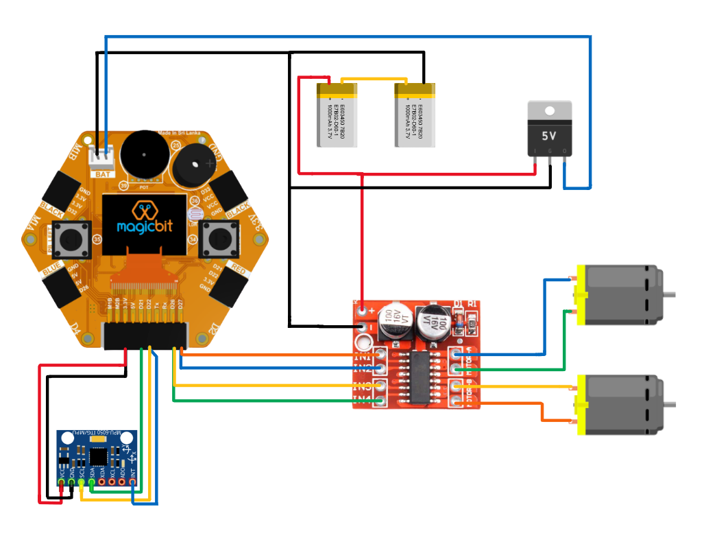
Hardware setupNow this is hardware setup part. The design of the robot is depends on you. When you designed robot's body you have to consider symmetric it about vertical axis which lies in motor axis. The battery pack located below. Therefor the robot is easy to balance. In our design we fix Magicbit board vertically to the body. We used two 12V gear motors. But you can use any kind of gear motors. that is depend on your robot dimensions.
when we discuss about circuit it's powered by 7.4V Lipo battery. Magicbit used 5V for powering. Therefor we used 7805 regulator to regulate battery voltage to 5V. In later versions of Magicbit that regulator is not need. Because it powering up to 12V. We directly supply 7.4V for motor driver.
connect all components according to below diagram.
In the code we used PID library for calculate PID output.
go to following link to download it.
https://www.arduinolibraries.info/libraries/pid
download the latest version of it.
To get better sensor readings we used DMP library. DMP stands for digital motion process. This is inbuilt feature of MPU6050. This chip have integrated motion process unit. So it takes reading and analysed. After it generates noiseless accurate outputs to the microcontroller (in this case Magicbit(ESP32)). But there are lot of works in microcontroller side to take that readings and calculate the angle. So to simply that we used MPU6050 DMP library. Download it by goint to following link
https://github.com/ElectronicCats/mpu6050
To install the libraries, in the Arduino menu go to tools-> include library->add.zip library and select the library file which you downloaded.
In the code you have to change the setpoint angle correctly. The PID constant values are different from robot to robot. So in tuning that, first set Ki and Kd values zero and then increase Kp until you get better reaction speed. More Kp causes for more overshoots. Then increase Kd value. Increase it by always in very little amount. This value is generally low than other values. Now increase the Ki until you have very good stability.
Select the correct COM port and board type the. upload the code. Now you can play with your DIY robot.


Comments