LoRa is a wireless technology that has been developed to enable low data rate communications to be made over long distances by sensors and actuators for M2M and Internet of Things, IoT applications.
One of the major issues for machine to machine, M2M communications used for applications like the Internet of Things, IoT is to enable communications over long ranges using very low power levels.
One scheme for addressing this is known as LoRa. It gains its name from the fact that it is able to provide 'LongRange' communications using very low power levels.
A LoRa network can be arranged to provide coverage similar to that of a cellular network. Indeed many LoRa operators are cellular network operators who will be able to use existing masts to mount LoRa antennas. In some instances the LoRa antennas may be combined with cellular antennas as the frequencies may be close and combining antennas will provide significant cost advantages.
LoRa TechnologyThere are several key elements of the LoRa wireless system. Some of its key features include the following:
- Long range: 15 - 20 km.
- Millions of nodes
- Long battery life: in excess of ten years
LoRa technology consists of several elements:
- RF interface / physical layer : The LoRa physical layer governs the aspects of the RF signal that is transmitted between the nodes or endpoints, i.e. the sensors and the LoRa gateway where signals are received. It governs aspects of the signal including the frequencies, modulation format, power levels, signalling between the transmitting and receiving elements, and other related topics.
- LoRa network architecture: Apart from the RF elements of the LoRa wireless system, there are other elements of the network architecture, including the overall system architecture, backhaul, server and the application computers.
Long Range Wide Area Network ( LoRaWAN ) is a low power wireless networking protocol designed for low-cost, secure two-way communication with the Internet of Things. Key requirements of Internet of Things such as secure bi-directional communication, mobility, and localization services are achieved by LoRaWAN. This standard also provides seamless interoperability among smart “Things” without the need of complex local installations and gives back the freedom to the user, developer, businesses.
LoRaWAN network architecture is typically constructed in a star-of-stars topology in which gateways is a transparent bridge relaying messages between end-devices and a central network server in the backend. Gateways are connected to the network server via standard IP connections while end-devices use single-hop wireless communication to one or many gateways.
A LoRa network consists of several elements:
- End points: The endpoints are the elements of the LoRa network where the sensing or control is undertaken. They are normally remotely located.
- LoRa gateway : The gateway receives the communications from the LoRa endpoints and then transfers them onto the backhaul system. This part of the LoRa network can be Ethernet, cellular or any other telecommunications link wired or wireless. The gateways are connected to the network server using standard IP connections. On this way the data uses a standard protocol, but can be connected to any telecommunications network, whether public or private. In view of the similarity of a LoRa network to that of a cellular one, LoRa gateways may often be co-located with a cellular base station. In this way they are able to use spare capacity on the backhaul network.
- Server: The LoRa network server manages the network. The network server acts to eliminate duplicate packets, schedules acknowledgement, and adapts data rates. In view of the way in which it can be deployed and connected, makes it very easy to deply a LoRa network.
- Remote computer: a remote computer can then control the actions of the endpoints or collect data from them - the LoRa network being almost transparent.
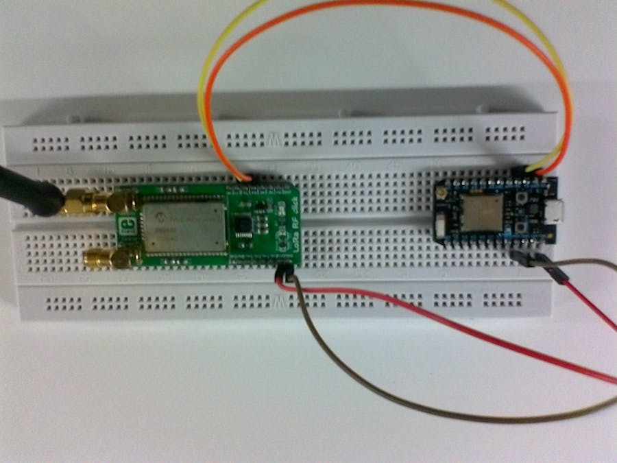
LoRa RF click carries Microchip’s RN2483 fully certified LoRa Sub-GHz, 433/868 MHz European R&TTE Directive Assessed Radio Modem. Two antenna connectors allow you to choose which of the two frequency bands will be employed. The RN2483 module has a specified range of > 15 km in rural and suburban settings, and > 5 km coverage in urban areas. A LoRaWAN™ Class A protocol stack is embedded (bidirectional end devices), as well as an ASCII command interface accessible through UART. The high receiver sensitivity can go down to -148 dBm. LoRa RF click communicates with the target board MCU through the mikroBUS™ UART interface (CTS, TXD, RXD), with the addition of a Reset pin (RST). The board is designed to use either a 3.3V or a 5V power supply.
LoRa DemoFor LoRa demo I used two platform. Mikroelektronika Flip&Click is used as LoRa sender, Particle Photon is used as LoRa receiver. In this demo, LoRaWAN is not implemented. LoRaWAN require concetrator/gateway. But, principle is here. LoRa gateway act as packet forwarder. Each packet from LoRa node is redirected to some server/cloud service. To simulate that, I used Particle.publish() function for sending data to Particle dashboard.
- Particle Photon and LoRa click
Connecting LoRa RF click to Photon is simple. From Photon you should provide power supply (3.3V) for LoRa RF. For serial communication, make usual connection TX->RX from one board to other.
- Flip&Click and LoRa click
Flip&Click has 4 slots for click boards. For this demo, Serial1 is used for communication with LoRa click. Put LoRa click in slot labeled with "1".


Comments
Please log in or sign up to comment.