


Hardware components | ||||||
 |
| × | 1 | |||
 |
| × | 1 | |||
| × | 1 | ||||
 |
| × | 1 | |||
Software apps and online services | ||||||
 |
| |||||
Watch the video tutorial.
Tired of staring at confusing sensor data? Meet Gus, the smart robot that makes monitoring your room's air quality, temperature, and humidity fun and intuitive! This little guy sits on your desk, using his animated eyes to show you the room's health. If conditions are poor, Gus gets sleepy. Keep him awake and energized by improving your environment! Open a window, adjust the thermostat, and watch Gus perk up. Let me show you how I made it!
Step 1: Prepare the Microcontroller & Test the Display Code
I started with a small piece of perfboard and soldered some female headers for the Xiao module. Applying some solder flux to the pins will help the solder stick better. Next, we’ll solder some wires to the female headers. Specifically, we need to connect wires to where the pins for D0, D1, D4, D5, 5V, and GND of the Xiao will be aligned after it is inserted into the female headers.
Once all the wires are soldered, it’s time to push the Xiao into the female headers. I previously soldered male headers onto the Xiao.
Next, use the provided Arduino code (eye_test.ino) to create two blinking ellipses on the OLED display, simulating Gus's eyes. Before uploading it to the Xiao, I tested it on an online simulator. After a bit of tweaking, it was starting to look pretty good!
Step 2: Connect the Display and Bring Gus's Eyes to Life
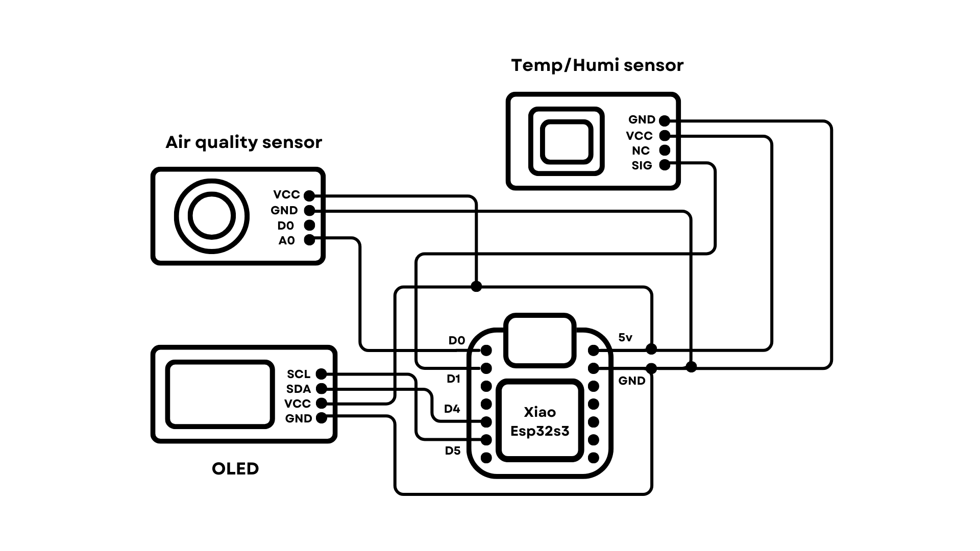
Connect the OLED display to the Xiao microcontroller. Connect the display's VCC pin to the 5V pin on the Xiao, the GND pin to the Xiao's GND, the SDA pin to the Xiao's D4 pin (I2C data line), and the SCL pin to the Xiao's D5 pin (I2C clock line). Finally, upload the tested eye animation code to the Xiao microcontroller. If everything is connected correctly, you should see Gus's animated eyes blinking on the OLED display.
Step 3: Prep the Air Quality Sensor
Before we start building Gus’s body, it’s a good time to get the air quality sensor ready.
If you check the documentation for the sensor, you'll notice that it suggests using a 20kΩ load resistor. However, the actual sensor module comes with a 1kΩ resistor. To fix this, I desoldered the 1kΩ resistor and soldered two 10kΩ resistors in series to replace it.
Now, we need to "burn in" the sensor. To do this, we’ll plug it into a 5V power supply and leave it running for at least 24 hours.
You see, these sensors have a heating element and a sensing material, typically made of tin oxide. Over time, impurities and moisture can build up on the sensing material, affecting its performance. By leaving it powered on for an extended period, the heating element warms up the sensing material, helping to burn off any impurities and moisture.
It’s a good idea to place the sensor in a well-ventilated area during this time to ensure good airflow and help clean the sensing material.
Step 4: Making the Head and Body
Cut a 5x5.5 cm rectangle from 5mm foam board for the face, and build a cuboid head by adding more foam pieces. Next, I cut a section out of the face for the OLED display, making sure the cut is slightly larger than the display itself.
Glue the pieces together, and trim excess. For the body, create a smaller cube to fit the Xiao board, with a slight slant for upward head movement. Make the legs with L-shaped foam board pieces.
Step 5: Eye Section and Painting
Now, for the eye section, I cut a piece of plexiglass to match the size of the cutout on the face.
Next, apply a rectangular piece of masking tape on one side of the plexiglass, making sure it's the exact same size as the OLED display.
Once that’s done, we can paint the entire thing with black acrylic paint. Just be sure the masking tape is securely pressed down and doesn’t shift while you paint!
While that’s drying, paint the edge of the eye section, as well as the inside of the head black. This will help prevent any reflections when the eyes light up.
I also painted the entire body white to cover up any seams and leftover pencil markings.
Step 6: Test the Air quality andDHT22 sensors
After letting it sit for 24 hours to burn in, we can connect female jumper wires to the VCC, GND, and analog out pins of the air quality sensor.
And then connect the corresponding wires to the Xiao. Before uploading the code, we need to calibrate the sensor.
Use the below code to read the R0 values. Now once you got the R0 values, Go to Documents > Arduino > libraries > MQ135-masterfolder and open the MQ135.h file and change the RLOAD & RZERO values. RLOAD will be 20.
Once calibrated, upload the MQ135_get_ppm.ino code to get the air quality index in PPM.
Next, we repeat the steps to test the humidity and temperature sensor. This one doesn’t require any calibration.
Just upload the code (test_DHT.ino), and the humidity and temperature values should start displaying right away.
Step 7: Assemble
Great! Now that all the sensors are tested, it’s time to assemble everything.
I started by sticking the OLED display right behind the cutout on the face using double-sided tape. The screw hole was sticking out, so I carefully trimmed it off with pliers.
Peel off the masking tape from the painted plexiglass and stick it in front of the cutout with glue. I also made two foam board discs for his ears.
Next, I attached the Xiao board inside the small body using more double-sided tape. I earlier made a cutout to let the USB-C cable in. For the head, I made a back plate from the same 5mm thick foam board and created cutouts for the sensors. I placed the sensors in their spots, and then connected all the wires.
I then used electrical tape to secure the connections and prevent any shorts. Finally, I glued all the body parts together.
Step 8: Upload the main code
Now, connect a USB-C cable to the Xiao and upload the main code.
The Code reads the values from the DHT22 sensor. Then it reads the air quality sensor values, and uses the DHT22 sensor readings to get the corrected AQI in PPM. It has a function to blink the eyelids once every 3 to 5 minutes (Selected at random). It calculates a "comfort score" based on how good the readings from the sensors are. And it maps the eyelid height to the comfort score. The worse the score, the lower the eyelid goes.
Sometimes, you might get an error while uploading the code to the Xiao. To fix this, press and hold the boot button on the Xiao before plugging it into the PC. Keep holding the button while you plug it in, and once the upload window says “connecting ”, release the button. The code should upload successfully. You might want to do this before sticking the Xiao inside the body.
Take Care of Gus, Take Care of Yourself :)As soon as the code is uploaded, the eyes should light up on the display. Gus looks absolutely amazing with those animated eyes randomly blinking. And now, thanks to the sensors, his eyes will reflect his mood based on the surrounding conditions.
Honestly, I think the foam board body looks a bit unfinished, and I’d prefer a 3D-printed body instead. I’m also planning to upgrade Gus with more features, like a touch sensor on his head. You’ll be able to touch his head to show the sensor values in place of his eyes when you want to know more. Also, a light sensor can be added, so Gus can get gloomy on cloudy, dark days.
Let me know your thoughts in the comments :)


Comments