


Hardware components | ||||||
 |
| × | 1 | |||
 |
| × | 1 | |||
 |
| × | 1 | |||
 |
| × | 1 | |||
 |
| × | 1 | |||
| × | 1 | ||||
 |
| × | 1 | |||
 |
| × | 1 | |||
 |
| × | 1 | |||
 |
| × | 1 | |||
Software apps and online services | ||||||
 |
| |||||
 |
| |||||
| ||||||
Hand tools and fabrication machines | ||||||
 |
| |||||
 |
| |||||
 |
| |||||
 |
| |||||
 |
| |||||
 |
| |||||
I always wanted to build my own version of mobile robot platform. The original plan is to develop a robotic platform that is modular, easy to build and integrate with off-the-shelves components like Arduino and Raspberry Pi.
But my goal pivot to other interesting topic, "Pick and Place Robot". I know that this application has been around for a long time already, but I observed that there is a little or no presence for Philippines on related fields like logistics, warehouse management, manufacturing, etc. The video below shows my implementation of object following/tracking using OpenCV on the Raspberry Pi.
Makibot is now on development track for this application. The fundamental concept is to create a mobile robot that can move to its surroundings, find specific object using marker, get the object, and transfer to the designated location. Imagine hundreds of this robot working at same time to sort online orders. With the crisis we are currently experiencing (COVID-19). A tool like this will reduce human physical contact to minimize the risk of the virus.
[UPDATE: 5/26/2020]
A major iteration is needed for this project. Because our goal is to make a robot that deliver object to specific area, lifting or gripping the object will require significant amount of accuracy and safety, thus will make this project a little complicated over time. Instead of using forklift or gripper to deliver the object, we can manually(or auto-drop mechanism) place the object on the robot carrier platform. Then, when it reached the location or bin, the robot will lever the carrier to drop the object to the bin.
How?Since this project is under development, this page will serve as platform for project logs and planning. You'll see the current progress and issues of this project.
The list below will show the things we have done so far.
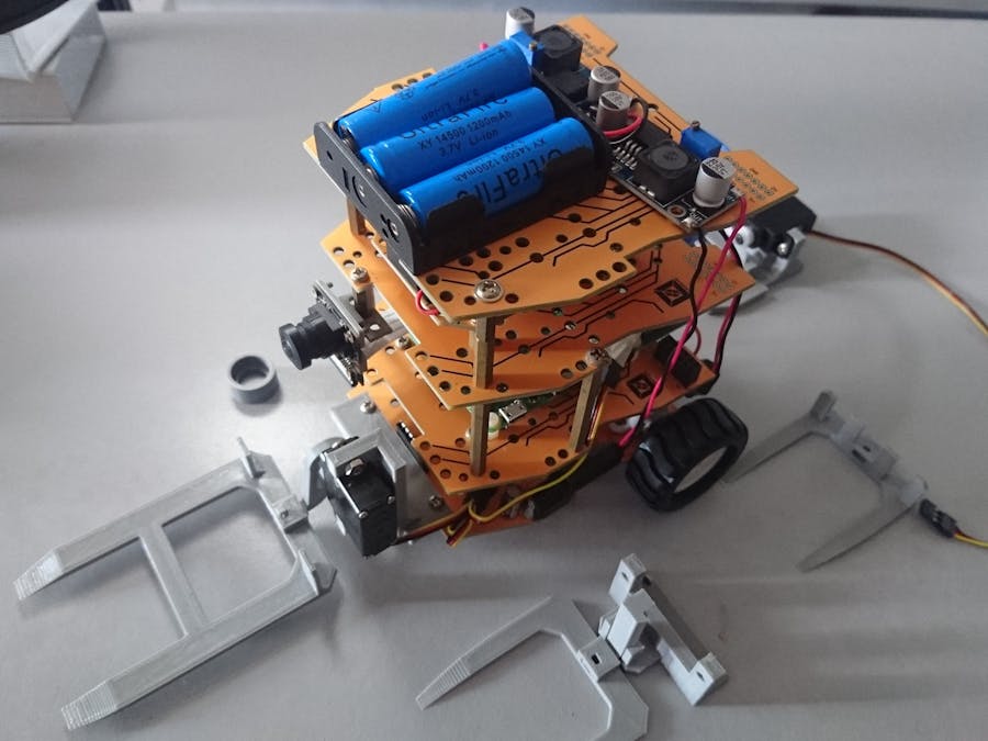
1. Makibot Chassis
First and foremost, we designed and fabricated my own robot chassis. The main material is PCB. The lowest layer is where the Arduino and motor driver is located. Second layer is where my SBC is installed, we are currently making experiments on Raspberry Pi with Ubuntu Mate OS. The third and fourth layer is for power system ( Battery, DC-DC step module, charge module). Second up to fourth layer are custom PCB with holes to accommodate modules and boards for faster integration and installation.
NOTE: My future plan is to make the power system and mechanical drivers on the lowest layer. It is so hard to access GPIO when SBC and microcontroller are on the lower layer.
[UPDATE: 5/25/2020]
I observed that when the robot has a box on its forklift, the box is partially blocking the view. Thus, I decided to put the camera on the back instead. The rear is now the front for navigation, and when the robot has to pick something, it will turn 180 degrees angle to let the forklift pick the object properly.
2. Power System
The idea is to have a separate power supply for mechanical drivers and controllers/sensors/communication modules. Of course, each power supply is in common ground. For my current setup, Raspberry Pi and Arduino is being powered by a single and boosted 18650 li-ion battery. Motors are being powered by 3 series 14600 and buck converter.
3. SBC and microcontroller
Currently, we have Raspberry Pi 3B as main computing platform. It has Ubuntu Mate OS and ROS installed. With respect to the goal, we want this board to perform machine vision function. Having said that, OpenCV is already installed as part of ROS packages. We also installed and tested Aruco for marker detection. Test codes are already up in Github. We are also leaning towards the use of NVIDIA Jetson Nano since it has better performance when it come to machine learning and computer vision.
We also have Arduino Nano to handle mechanical driving and controls. Since it has limited memory and low computing power. We are thinking of replacing it by ARM microcontroller or totally getting rid of it and just use control board that can communicate using I2C or SPI protocol on my Raspberry Pi.
4. Camera
We are using a wide angle Rpi Camera. No plans on using other camera sensor.
5. Motors and Drivers.
The robot is using an N20 motor and being driven by L293D IC. I think, it is enough for my current setup, but if we want a usable robot, a heavy-duty motor and high-current H-bridge driver is required. We are also using a servo motor with all-metal gear.
6. 3D Printed Parts
This portion of development is quite interesting and time consuming. We are developing a simple pick-and-place mechanism using 3D modelling application and an FDM 3D Printer. My first design was a single servo gripper. It was working as it was but can only handle smaller objects. We have to increase the servo if we need to increase its capacity. Unfortunately, we are limited to small servo at this moment.
Hence, we investigate on making my own version of fork-lift since it was close on what industry is using when it comes to indoor mobility. Here is the first version. See image below. But it is not working very well since it has low vertical actuation range.
The last design is a bit off to what forklift is. But at last, it is working pretty great. To test this mechanism, we also prepared a box type container. each face will have a marker.
7. Function
We have achieved making the robot move using teleop control, utilize camera and aruco_ros to detect a marker, make the robot navigate to that marker.
[will add video here]
8. Plans
Milestone I:
a. Make the robot pick the object.
b. Navigate to specific place and drop the object.
c. Go back to start position
Hardware Upgrade
a. Add important sensors(MEMS, Lidar, Motor encoder)
b. Redesign chassis architecture
c. Find better wheels and motor
d. Buy NVIDIA Jetson Nano
e. If we still need MCU, we might but STM32 Bluepill or Teensy Board. (Please advise if you experience with this matter)
I think that is all for now. We will constantly update this page if achieve major development.
You can like my facebook page.


_3u05Tpwasz.png?auto=compress%2Cformat&w=40&h=40&fit=fillmax&bg=fff&dpr=2)

Comments
Please log in or sign up to comment.