


Hardware components | ||||||
_ztBMuBhMHo.jpg?auto=compress%2Cformat&w=48&h=48&fit=fill&bg=ffffff) |
| × | 1 | |||
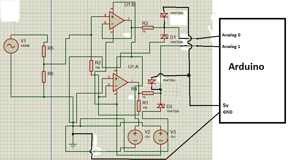
This Arduino oscilloscope makes use of two analog read pins. When the tension of the source is positive ( 0 to 5v ) the signal passes throght the non inverter op amp and enters in analog read 0 and the value appears above the 0 line in graphical oscilloscope. When the tension of the source is negative (0v to -5v), it passes through op amp wich invert the signal to positive. That positive tension enters in analog read 1. Now, when when we have positive tension on analog read 0 ( that means analog read 1 is 0v ( because arduino can't read negative tension )) and so the code in the arduino should represent the value on analog read 0 above the line of 0v in graphical oscilloscope. When we have positive tension on analog read 1 ( that means analog read 0 is 0v ), the code in the arduino should represent the value on analog read 1 below the line of 0v in graphical oscilloscope.
Be very wise when choosing the op amps. This op amp should be chosen considering the type of signals that you gonna use.
You can use one of those old ATX power supplys to provide +12vdc and -12vdc.
If you have to step down the voltage of the source make a tension divider with resistors before the signal enters in the op amps.
This can also be usefull for analising data packets of data transfer protocols that uses positive and negative tensions.
Remember, this is just an idea, you will have to develop the graphical interface of the oscilloscope. I don't have the knowledge to do that part.


Comments
Please log in or sign up to comment.