Due to global Covid-19 pandemic forcing many people to remain at home, the current attention on patient-centered care is becoming more dependent on virtual medical treatments. Many elderly people who have chronic diseases, require frequent check-ups and need to be continually monitored. It is time-consuming for them to drive back and forth to visit physicians, and alternatives such as in-house care are unreasonably expensive for the majority of patients. There is also an increased risk of exposure to Covid-19, which can be risk for the elderly people. These factors have led to the increased adoption of remote patient monitoring.
Before the detailed documentation, I have attached my project: Healthconnect demo and its feature in below YouTube link, Kindly watch it.Some of the barriers in present health care system across the Globe:
- Rural residents often encounter barriers to healthcare that limit their ability to obtain the care they need. In order for rural residents to have sufficient access, necessary and appropriate healthcare services must be available and obtainable in a timely manner.
- Outpatient health checkup and treatment got widely affected during Covid-19 times. Many elderly people doesn't get enough medical consultation during these pandemic days, which makes their health condition even more worsen.
- People who have chronic diseases, require frequent check-ups and need to be continually monitored. It is time-consuming for them to drive back and forth to visit physicians.
I have developed a Wearable Medical device powered by AVR-IoT Microchip.
The HealthConnect will have the below features:
HealthConnectis a wearable IoT medical device powered by AVR-IoT microchip which can be wore around your arm. It streams your health data - ECG, Heart Rate, SpO2, Body Temperature, Activity Status, Ambient Temperature over a secured AWS platform.Real time data monitoring helps to diagnose the patient condition better in online consultation with physician. This device can be connected to your mobile phone through HealthConnect android app, which has a feature to send SOS to your family /Doctor with a link to monitor your health data instantly. This SOS feature can helps to provide first Aid in medical emergency.Architecture
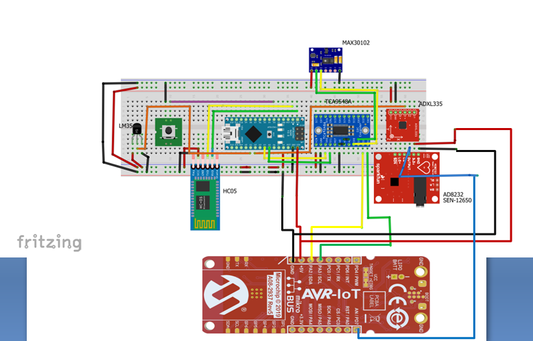
The complete architecture with communication interface is mentioned in below diagram.
I have used two microcontrollers in the HealthConnect device. The master controller will be AVR IOT WA and secondary controller will be Arduino Nano to read more analog input signals ( LM35, ADXL335).The device has external Bluetooth connectivity through HC-05 for SOS operations.
Let's build the HealthConnect deviceI have made a HealthConnect: Making video with brief description about how I made this device from scratch to product. Before proceeding with detailed instructions, you can watch the below making part YouTube video.
1. Getting started with AVR IoT WA1.1Connecting it to PC
Connect the AVR IoT to the PC and you will get pop up window. Open the CURIOSITY drive in My computer.
1.2For first time connection follow the below step
Wi-Fi credentials download
Enter your Wi-Fi credentials and download the WIFI.CFG file. Then Drag and drop the file into CURIOSITY folder.
(OR)
Create a file WIFI.CFG, Replace XXXX, YYYY with Wi-Fi credentials then drag and drop into CURIOSITY folder.
1.3 Download Latest Firmware.hex file
If there is connection issue with your WiFi network after following step 1.1 and 1.2, flash the latest firmware.hex file.
Get the latest firmware by clicking CLICK-ME.htm in CURIOSITY and download the hex file.
Useful Links : https://ww1.microchip.com/downloads/en/DeviceDoc/30010218B.pdf
2. Software RequirementsInstall the below mentioned software's for Working on AVR IoT
Download the source code from below link
Link : https://github.com/microchip-pic-avr-solutions/avr-iot-aws-sensor-node-mplab
The source code will have the same operation of sending Light, Temp data for every 1 second to AWS cloud, as you seen in CLICK-ME.htm.
3. Connecting ECG sensor AD8232 with AVR IoTThe ECG is separated into two Intervals
- PR Interval
- QT Interval
3.1 ECG Sensor AD8232
The AD8232 Heart Rate Monitor breaks out nine connections from the IC that you can solder pins, wires, or other connectors to. SDN, LO+, LO-, OUTPUT, 3.3V, GND provide essential pins for operating this monitor with AVR IOT WA
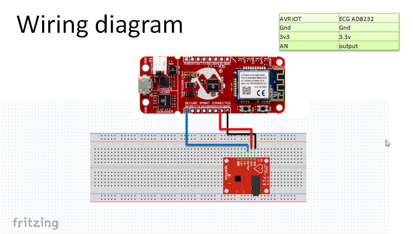
3.2 Interfacing AD8232 with AVR IoT
Connect it as per the below wiring diagram
3.3 Coding in MPLAB X IDE
Open the downloaded source code project and then import the AVRIoT.x
Create a new function for ECG reading in Sensors_Handling.c
#define ECG_SENSOR_ADC_CHANNEL	    7 // AN pin number is 7

uint16_t SENSORS_getEcgValue(void)
{
    uint16_t EcgVal=ADC0_GetConversion(ECG_SENSOR_ADC_CHANNEL);

    return EcgVal;
}
And call this function in application_manager.c file.
The ECG electrodes are placed in RA,LA and LL as mentioned in above diagram and connect the jack to the AD8232 sensor on the HealthConnect device.
Info: To get best results – Place electrodes on the chest wall equidistant from the heart (rather than the specific limbs)3.4 Graphical data in AWS
The data sent to AWS cloud can be visualized in browser and I have attached the snapshot of it below.
I have explained briefly about how to send data in less time interval (<1000ms) in Tips & Tricks section.
4. JSON edit for Data VisualizationAll the sensors data will be sent to cloud in JSON format. we need to append the ECG data in the existing JSON. In this section we will see how to edit JSON for your application.
Final JSON for my application is mentioned below :
len = sprintf(json,"{\"Ambient Temp\":%d.%02d,\"ECG Graph\":%d,\"Body Temperature\":%d,\"ActiveStaus\":%d,\"Heart Rate\":%d,\"spO2\":%d}",rawTemperature/100,abs(rawTemperature)%100, ecg,bodyTemperature,ActiveStatus,heartRate,spO2);Create new variable ECG Graph as \"ECG Graph\":%d and add it to the existing JSON by separating with comma ', '.
It is similar like sprint function with following JSON format.
5. Interfacing MAX30102 with Arduino NanoThe MAX30102 pulse oximeter is an Arduino-compatible and inexpensive sensor that permits calculation of heart rate.
5.1WiringDiagram
Note: In a final Component assembly, the wiring connection will differ from below. This section explains the normal connection between Arduino and MAX30102, not the Healthconnect wiring. Complete wiring will be explained in Section 6.
5.2 Coding
I have added GitHub link for the Arduino code interfacing with MAX30102, ADXL335 and LM35.
Pre Requirements:
For secondary controller , we need to install SparkFun_MAX3010x_Pulse_and_Proximity_Sensor_Library from Arduino library manager. It supports the MAX30102 sensor module.
5.3 Flowchart
I have added the logical flow diagram for heart rate and SpO2 calculation.
There is a default function ( maxim_heart_rate_and_oxygen_saturation) to calculate HR and SpO2 in Arduino. Below flowchart explains the programming logical flow for calculating heart rate and SpO2.
5.4 Why secondary controller needed?
AVR IoT needs to send data in a cycle time ( <1000ms) to AWS cloud, since ECG data needs to be sent with less delay time and parallelly Oximeter data read will takes 10 to 30 sec reading time.
- I want my device to communicate periodically (<1000ms) without any interruption. So I have introduced secondary controller to calculate SpO2, Heartrate.
- Also some of the I2C address is common between MAX30102 and ATECC608A
- Oximeter functionality will be standalone, it can be plugged in / out based on our requirement.
To satisfy above requirements, I have introduced secondary controller (Arduino Nano), where it will periodically calculates SpO2, HeartRate and body temperature. The master controller AVR IoT will act as master in I2C bus, where Arduino as I2C slave to transfer the calculated SpO2, HR, Temp and activity status.
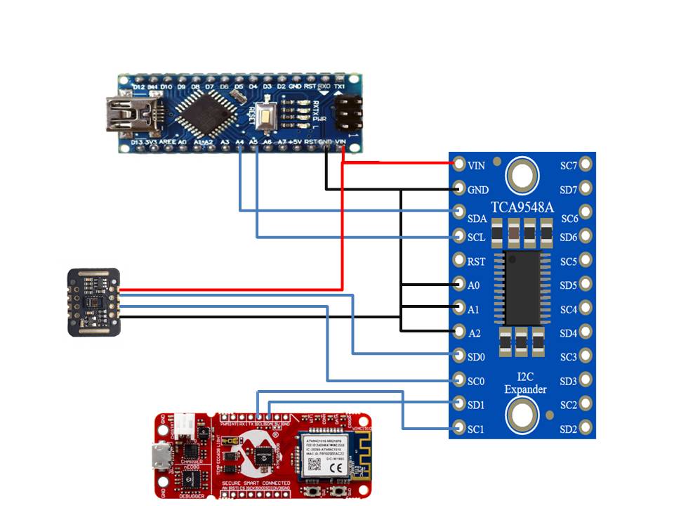
6. I2C MUX CommunicationCommon I2C bus communication is not possible between Arduino Nano, AVR IoT and MAX30102 due to I2C address conflict. I2C MUX - TCA9548A is used to resolve the I2C address conflict issue.
MAX30102 is connected to SC0, SD0 pins (Channel 0) of TCA9548A.
AVR IoT is connected to SC1, SD1 pins (Channel 1) of TCA9548A
When A0, A1, A2 of TCA9548A is connected to Gnd, the I2C address will assigned as 0x70 for TCA9548A . To switch the I2C channel , the secondary controller (Nano) can communicate to the TCA9548A through address 0x70.
//I2c multiplexer
void TCA9548A(uint8_t bus)
{
  Wire.beginTransmission(0x70);  // TCA9548A address is 0x70
  Wire.write(1 << bus);          // send byte to select bus
  Wire.endTransmission();
}
To communicate to the MAX30102, data sent to I2c Mux is 0 [ex: TCA9548A(0); ]
To communicate to the AVR IoT, data sent to I2c Mux is 1 [ex: TCA9548A(1); ]
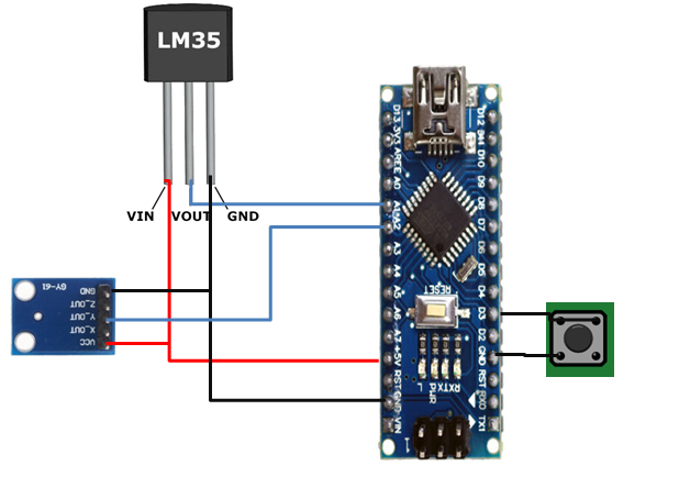
7. LM35, Tactile switch and ADXL335 interface with Arduino NanoI have added snippet code of integration of these elements to the Arduino below.
All the code will be collectively grouped under single Arduino code (Refer attachments)
LM35 coding part
const int sensor=A1; // Assigning analog pin A1 to variable 'sensor'

// Body temperature measurement
  vout=analogRead(sensor); //Reading the value from sensor
  vout=(vout*500)/1023;

  tempf=(vout*1.8)+32; // Converting to Fahrenheit

  bodyTemperature=abs(tempf);
Interrupt Tactile switch coding Part
const byte interruptPin = 3;

//In setup
pinMode(interruptPin, INPUT_PULLUP);
attachInterrupt(digitalPinToInterrupt(interruptPin), SOS, FALLING);


// SOS call

void SOS() {
  if(startupSOS==1)
  {
    SOSEnable=0;
    startupSOS=0;

  }
  else
  {
SOSEnable=1;
  }
}
Activity status Coding part
//Active status
  float Yout=0;
  float YoutPrev=0;
  const int YAxis=A2; // Assigning analog pin A1 to variable 'sensor'

//Setup
pinMode(YAxis,INPUT); // Configuring sensor pin as input

//Y-Axis Status

  Yout=analogRead(YAxis); //Reading the value from sensor
  Yout=(Yout*500)/1023;
  if(Yout>YoutPrev+50 || Yout<YoutPrev-50)
  {
active=1;
YoutPrev=Yout;

  }
  else
  {
    active=0;
    YoutPrev=Yout;

}When there is an emergency situation, The SOS button can be long pressed for 3 seconds. The HealthConnect device will send trigger message to HealthConnect App in the mobile phone. This app will send GPS data and Weblink of the health connect device to the Doctor/ family.
9. HealthConnect Android App
I have developed an Android app using MIT App Inventor. The App will have feature to connect it to HealthConnect device through Bluetooth and When SOS is triggered in HealthConnect device, The App will send the GPS and Weblink of AWS cloud - the sensor data streaming to the contact selected in App.
I have attached App project file with this project.
10. I2C Master /Slave Communication in AVR IoTAVR IoT will be assigned as Master in I2C and Nano will be assigned as Slave device.
Create a new function I2cReading in sensors_handling.c to read the HR, SpO2, Body temperature and Activity status from Nano.
#define SECONDARY_DEVICE_ADDR    0x07 // Arduino Nano

void I2cReading(void)
{

            i2c_readNBytes(SECONDARY_DEVICE_ADDR,&I2cData,5);

}
Add the below patch of code in application_manager.c
To access the same buffer in different C file, I have used extern type { extern uint8_t I2cData[5] }. Copy and paste the below code in sensors_handling.h file
#ifndef SENSORS_HANDLING_H
#define SENSORS_HANDLING_H
#include <stdint.h>

uint16_t SENSORS_getLightValue(void);
int16_t SENSORS_getTempValue (void);
uint16_t SENSORS_getEcgValue(void);
void I2cReading(void);
#define BodyTemperature_ADDR 0
#define ActiveStatus_ADDR 1
#define HeartRate_ADDR 2
#define Sp02_ADDR 3
#define MotionStatus_ADDR 4


extern uint8_t I2cData[5];

#endif /* SENSORS_HANDLING_H*/
I2C Slave - secondary controller
In Arduino Nano , I2C request event will be called whenever the AVR IoT requested the I2C call.
// function that executes whenever data is requested by master
  // this function is registered as an event, see setup()
  void requestEvent() {

    //bodyTemperature=bodyTemperature<<8;
    I2CData[0]=bodyTemperature;
    I2CData[1]=active;
    I2CData[2]=heartRatedata;
    I2CData[3]=SpO2;


    //I2CData=(bodyTemperature|height);
    Wire.write(I2CData,4); // respond with message of 4 bytes
    // as expected by master
}The AVR IoT source code will transfer the data to AWS cloud in 1000ms time interval. In my application, The ECG data needs to be transmitted in lesser interval of time. I have modified some parameters in source code to reduce the time interval.
Note: Based on the application, this can be modified.
By Default the interval time CFG_SEND_INTERVAL is 1
I have reduce it to 0.5 in IoT_Sensor_Node_config.h
Also Note, The main thread is called for every 100ms only. It can be reduced to lesser time by changing the MAIN_DATATASK_INTERVAL in application_manager.c file. But lesser time interval for sending data to AWS cloud makes unstable.
The final output which can be seen in Doctor's PC/mobile while scanning the QR code is attached as screen shot below.
This methodology makes the Virtual consultation more simple , Where any elder patients who might difficulty to interact with doctor's in virtual call can also show the QR to make the interaction simpler and smarter .13. Power Supply
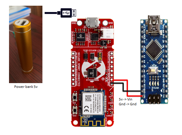
I have used 5v Power bank case with Li-ion 18650 battery. This module can be charged through normal Mobile phone charger. Size ( L = 9 Cm, W = 1.5Cm), so it can be easily portable and placed in wearable kit without occupying much space.
The Power bank is connected to the master controller AVR IoT through USB and Nano gets powered from AVR IoT from 5v output of AVR IoT. The power connection between AVR IoT and Nano is illustrated in below diagram.
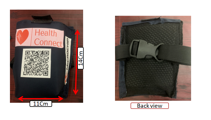
The HealthConnect device is placed in customized bag which can be wore around your arm.
I will make use of TinyML application and train the device with more ECG Data and Heart Rate to predict the cardiac inflammatory disease in early stage.
HealthConnect is a simple and Secured IoT medical device where anyone can use it without any complex operations. For Elder people , The QR code Scanning method makes their interaction to Doctor's in virtual call even more simpler and Effective with health data streaming. The SOS functionality will help them to communicate instantly during emergency situations.
For Young people, The real time ECG streaming will helps to evaluate their performance in athletic sports




_3u05Tpwasz.png?auto=compress%2Cformat&w=40&h=40&fit=fillmax&bg=fff&dpr=2)


Comments
Please log in or sign up to comment.