your soldering iron or glue gun? I did!
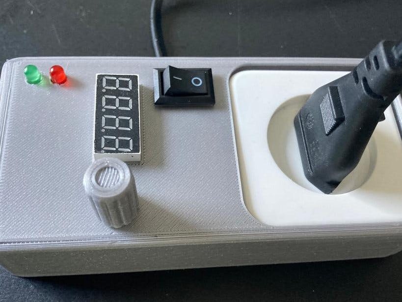
What if there was a simple device that does it for you? Wouldn’t it be too much work to set it properly? Not his one. If you turn the knob a tiny bit it displays the number 1 and powers on the connected AC device on for 1 minute. If you turn further(or the other way), you can set it to a maximum of 255 minutes. The last minute the red led starts to blink and you can add more time or leave it. Finally, the connected device is turned off automatically.
Components.
The star of this timer is the rotary encoder. I always wanted to use the one I had lying around but never succeeded in getting it to work until I found an Arduinoscript that does. Somehow it uses interrupts, and I don’t understand exactly how but it works perfectly. You can use any Arduino or lookalike as long as you use pin 2 & 3. I like to use an on/off button, but it is not mandatory. It turns on the small power supply that powers the Arduino and the green led. The 5v relays turns on the 110/230V device connected to the cheap build on wall outlet and the red led. The relay is glued on the back of the seven segment display with a small piece of plastic in between (which is included in the 3D printer parts). Latest version of the 3D parts here: https://www.thingiverse.com/thing:5020051 Be careful to protect all 110/220v cabling against touching. I soldered 2 female headers for the Arduino on a small perfboard (so you can take the nano out for programming). You can use a breadboard if you like. The casing I designed in Tinkercad and 3D-printed it on my Prusa MK3s. I will share the design with this project and soon on Thingiverse(for tips and remakes). There are probably standard cases you can use instead.
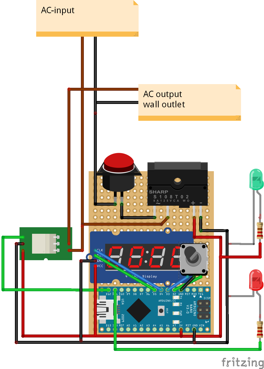
The schematic is pretty simple. The rotary uses GND and pins 2 & 3 (mandatory). The pinout may vary. Checkout your specs which one is GND (probably the middle one). The other 2 don’t mind (you can switch them for direction change probably). The TM1637 4 digit seven segment display has 4 pins:
VCC = pin 5V
GND = pin GND
CLK = 4
DIO = 5
CodeAs stated above the rotary-part (void PinA and void PinB) was not written by me but is publicly shared. The rest of the code is mine and pretty straight forward.
ImprovementsThe design of the case is not very trendy. The push function of some rotaries could be used for a buzzer signal.


Comments
Please log in or sign up to comment.